5-64
5
11. Connect the engine ECM coupler.
NOTICE: Make sure that the rubber
seal is installed properly in the engine
ECM coupler.
12. Install the engine ECM, and then tighten
the engine ECM bolts to the specified
torque.
13. Install the engine ECM cover.
14. Connect the neutral switch coupler.
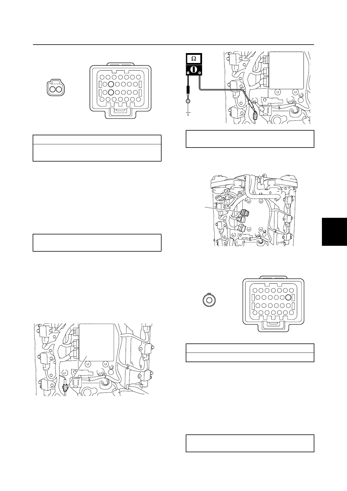
Checking the knock sensor
1. Remove the engine ECM cover.
2. Disconnect the knock sensor coupler a.
3. Measure the knock sensor resistance.
4. Remove the engine ECM, and then dis-
connect the engine ECM coupler b.
5. Check the wiring harness for continuity.
6. Connect the engine ECM coupler.
NOTICE: Make sure that the rubber
seal is installed properly in the engine
ECM coupler.
7. Install the engine ECM, and then tighten
the engine ECM bolts to the specified
torque.
Wiring harness continuity:
a Terminal 1–e Terminal 12
a Terminal 2–e Terminal 18
Engine ECM bolt:
7 N·m (0.7 kgf·m, 5.2 ft·lb)
1
2
e
a
18
12
a
Knock sensor resistance (reference data):
504.0–616.0 kΩ at 20 °C (68 °F)
Wiring harness continuity:
a Terminal 1–b Terminal 8
Engine ECM bolt:
7 N·m (0.7 kgf·m, 5.2 ft·lb)
b
b
a
8
1
Ignition unit and component

 Loading...


