ELECTRICVEHICLE-MOTORMotorInstallation
16
8.Makesurethearmatureturnsfreely.Ifitdoesnotturnfreely,disassemblethemotortondtheproblem.
MOTORINSTALLATION
SeeGeneralWarningsonpage1-2.
1.Cleanthetransaxleinputshaft.
1.1.SpraytheinputshaftthoroughlywithCRC
®
Brakleen™orequivalentbrakecleanerdegreaser.
1.2.Wipeinputshaftwithacleancloth.
1.3.Inspectthegroovesoftheinputshaftandremoveanyremainingdebris.
1.4.Repeatsteps1.1through1.3untilinputshaftisclean.
2.Lubricatethetransaxleinputshaft.
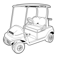
2.1.Squeezeapproximately1/2inch(1.3cm)ofmoly-teonlubricantfromtubeontoaputtyknifeasshown
(Figure16-20,Page16-15).
2.2.Rotatewheelstorotateinputshaft.
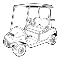
2.3.Applymotorcouplinggreaseevenlytotherotatinginputshaftstartingatapproximately1/8inch(3.1
mm)fromtheendoftheshaftandworkingbacktowardthetransaxle(awayfromtheendoftheshaft)
(Figure16-21,Page16-15).
2.4.Thegreaseshouldbeevenlydistributedinthegroovestoawidthofapproximately3/8inch(9.5mm).
2.5.Useaatscrewdrivertocleanthegreaseoutofoneofthegroovesandallowairtoescapewhenthe
motorispushedontotheinputshaft.
1
2
1
1/2
mm
inch
1/8 INCH
(3.1 MM)
3/8 INCH (9.5 MM)
741
Figure16-20GreaseonPuttyKnife
742
Figure16-21ApplicationofgreasetoInputShaftGrooves
2.6.Checkthechamfer(1)andend(2)oftheinputshafttoensuretheseareasarecompletelycleanofgrease
asshown(Figure16-22,Page16-16).
3.Installthemoldedbumper.
3.1.Withtheatsidetowardthebottomofthecouplingandthecuppedsidetowardthetransaxleinputshaft,
installthemoldedbumper(30)intothemotorcoupling(Figure16-15,Page16-12).SeefollowingNOTE.
NOTE:Themotorcouplingandthenewmoldedbumpermustbefreeofgreaseanddebris.
3.2.Ensurethattheinstalledbumperisseatedatthebottomofthecoupling.
2020Precedent,Villager2and4MaintenanceandServiceManualPage16-15

 Loading...