23
DrivenClutchGASOLINEVEHICLE-CLUTCHES
8.Slidethethreadedboltassemblythroughtheclutchbodyuntilthethreadedboltandthrustcollarareagainst
thexedsheave.
9.Holdtheclutchassemblyandcaminstallationtooltogetherandplacethexedsheavedownonspacedblocks.
10.Installthecampressplate(13),thrustwasher(14),thrustbearing(15),thrustwasher(16),andnut(17)onto
thethreadedbolt.
11.Threadthenutdownontothecamhub,centeringthepresshubontothecamhub.
12.Holdthexedsheaveoftheclutchandrotatethemoveablesheaveoftheclutchone-thirdturncounterclockwise.
Thematchmarksmadebeforedisassemblyshouldnowalign.
13.Usetwowrenchesandholdthethreadedboltheadwhiletighteningthecampressplatetopressthecamontothe
keyedshaft.Advancethecampressplateuntilitisrmagainsttheshaftend.
WARNING
•Donotplacengersunderthecamwhenremovingthecam.Themoveablefacemayspinwhenthe
cambuttonsreleasefromthecamramps,resultinginseverepersonalinjury.
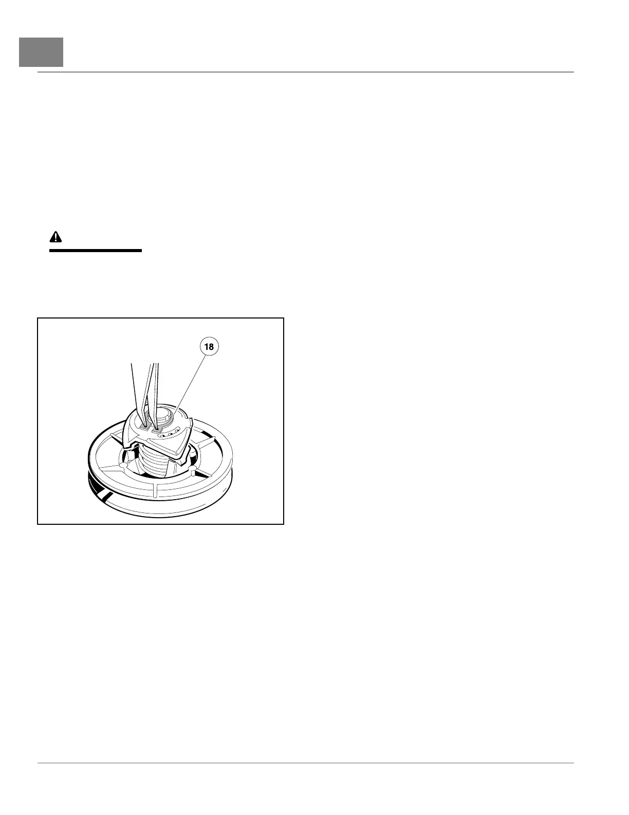
14.Installtheretainingring(18)(Figure23-22,Page23-18).
608C
Figure23-22InstallRetainingRing
15.Removethedrivenclutchtool.
DRIVENCLUTCHINSTALLATION
1.Toinstallthedrivenclutch,reversetheremovalprocedure.
2.Makesurethatthewasher(2)ismountedwiththeatportionofthewasheragainstthedrivenclutch(Figure
23-13,Page23-12).
3.Tightenthenewbolt(1)to18ft·lb(24.4N·m).SeefollowingNOTE.
NOTE:Thebolt(1)mustbereplacedwithanewboltcontainingalockingpatchthatwillpreventtheboltfromloosening.
4.Connectthebatteryandsparkplugwire.
Page23-182020Precedent,Villager2and4MaintenanceandServiceManual

 Loading...