18
ElectricalSystem
GASOLINEVEHICLE-TROUBLESHOOTING
ANDELECTRICALSYSTEM
SeeFuseandRelayLocationsonpage18-5.
_
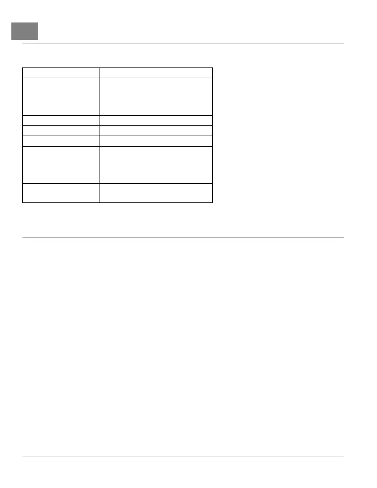
CALLOUTNUMBERDESCRIPTION
1
FuseHolder
•10AFuse
•5AFuse
•20AFuse
22AFuse
315AFuse
4FuelPumpRelay
5
FuseHolder
•7.5AFuse-Stereo,Visage
•4AFuse-Accent/Logo
•3AFuse-Headlights,T aillights
6
FuseHolder
•10AFuse-Horn,TurnSignal
ELECTRICALSYSTEM
Theelectricalsystemonthegasolinevehicleis12voltsDCwithnegative(–)groundtoframe,andconsistsofthe
followingcircuitsthatareeasilyidentied:
•StarterCircuit
•GeneratorCircuit
•ElectronicFuelInjectionCircuit
•EngineIgnitionCircuit
•EngineKillCircuit
•Multi-purposeBuzzerCircuit
•LowOilWarningLightCircuit
•NeutralLockoutCircuit
•FuelPumpCircuit
•FuelGaugeandSendingUnitCircuit
•HourMeterCircuit
•LightingCircuit
Recognizingandunderstandingthefunctionofeachofthesecircuitswillhelptoquicklyisolatethesourceofan
electricalproblem.Usetheappropriatetestproceduretocorrecttheelectricalproblem.SeeTestProcedureson
page18-7.
Page18-62020Precedent,Villager2and4MaintenanceandServiceManual

 Loading...