Tyres
Front (TC) ........................"Pirelli" 51R-MT 32A or "Dunlop" D756; 80/100 x 21”
Front (TE - TXC) ............................................. "Michelin" ENDURO COMP. 3 or
"Pirelli" MT 83 Scorpion; 90/90 x 21”
Front (TE USA) ................................................."Metzeler KAROO"; 90/90 x 21”
Rear (TC)
.................................................................."Pirelli" NHS (57) MT 32 or
"Dunlop" D756; 100/90x19”
Rear (TE - TXC) ............................................. "Michelin" ENDURO COMP. 3 or
"Pirelli" MT 83 Scorpion 120/90x18”;
Rear (TE USA) ..............................................."Metzeler KAROO"; 140/80 x 18”
Cold tyre pressure - Front (TC)
...............................................0.9-1.0 Kg/sq cm
Cold tyre pressure - Front (TE - TXC) (*) ................................0.9-1.0 Kg/sq cm
Cold tyre pressure - Front (TE) (%)
............................................... 1.1 Kg/sq cm
Cold tyre pressure - Rear (TC)
................................................0.8-0.9 Kg/sq cm
Cold tyre pressure - Rear (TE - TXC) (*) .................................0.8-0.9 Kg/sq cm
Cold tyre pressure - Rear (TE) (%)................................................ 1.0 Kg/sq cm
(*) Racing use - (%) Road use
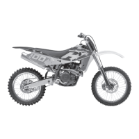
Electrical components location (TC)
The ignition system includes the following elements:
- Generator on the inner side of L.H. crankcase half cover;
- Electronic ignition coil under the fuel tank;
- Electronic control unit under the fuel tank;
- Spark plug on cylinder head;
- Throttle position sensor on carburettor.
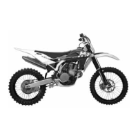
Electrical components location (TXC)
The ignition system includes the following elements:
- Generator on the inner side of L.H. crankcase half cover;
- Electronic ignition coil under the fuel tank;
- Electronic control unit under the fuel tank;
- Voltage regulator under the fuel tank;
- Spark plug on cylinder head;
- 12V-450W starter motor behind the engine cylinder;
- Solenoid starter on the left of rear chassis;
- M.A.Q.S. sensor (pressure, throttle position, air temperature) on throttle body.
The electrical system includes the following elements:
- 12V-6Ah battery under the saddle;
- Electric fan relay on right side of chassis:
- Electric fan;
- Two 15A and 20A fuses on right side of rear chassis;
- Coolant temperature sensor;
- Lambda sensor;
- Fuel pump inside the fuel tank.
- Fuel and reserve indicator.
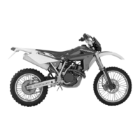
Electrical components location (TE)
The ignition system includes the following elements:
- Generator on the inner side of L.H. crankcase half cover;
- Electronic ignition coil under the fuel tank;
- Electronic control unit under the fuel tank;
- Voltage regulator under the fuel tank;
- Spark plug on cylinder head;
- 12V-450W starter motor behind the engine cylinder;
- Solenoid starter on the left of rear chassis;
- M.A.Q.S. sensor (pressure, throttle position, air temperature) on throttle body.
 Loading...