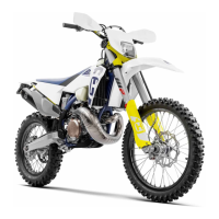
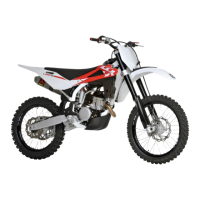
Fit screws and spacers (10) to temporarily secure the cylinder liner (7).
(3 spacers 10a, h= 44.2 mm; 1 spacer 10b, h= 29.2 mm)
Use a 12 mm wrench - 40 Nm, 4 Kgm, 29 ft/lb.
Make sure that the piston is at Top Dead Centre.
Measure distance "A" on the four machined faces of the piston and choose the
appropriate head gasket according to the table below.
Remove spacers and screws (10) and t the appropriate head gasket.
Cylinder head gasket selection table
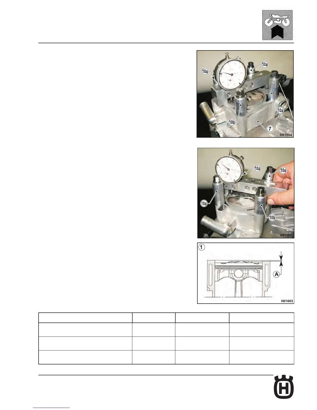
Bring piston to T.D.C. at the end of the compression stroke, measure distance “A”
between piston crown and head gasket mating face and select the appropriate
gasket according to the table below.
CONDITION (see diagram) “A” Gasket thickness Gasket part no.
1) (piston lower than cylinder mating face) -0.1 ± 0.05 mm 0.7 mm 8B00 A6576
1) (piston lower than cylinder mating face) -0.2 ± 0.05 mm 0.6 mm 8A00 A6576
1) (piston lower than cylinder mating face) -0.3 ± 0.05 mm 0.5 mm 8000 A6576
 Loading...