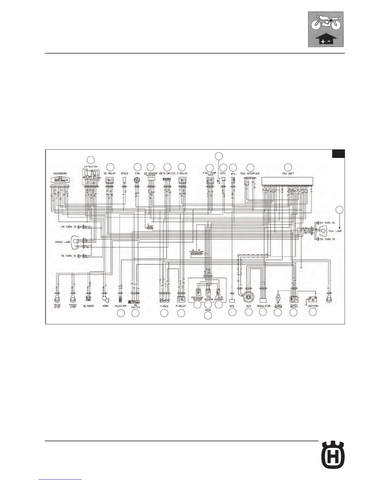
Ignition system (TE - TXC)
The ignition system is controlled by the ECU (1). The ignition is an integrated
digital electronic ignition system with static timing and advance using intermittent
sequential phased electronic injection feed. This ignition system is composed
of a crankshaft position (pick-up) sensor, an ECU, an ignition coil and an intake
manifold pressure sensor. The ignition coil is fed by the battery through a power
relay and is controlled by the ECU. Ignition timing is accurately determined based
on engine RPM and accelerator position.In addition to these key parameters,
inputs from the intake air temperature and pressure sensor and from the coolant
sensor are also used to control ignition timing.
Key
1. Electronic control unit
2. Alternator
3. Voltage regulator
6. Injector
10. Cooling fan
13. L.H. switch
15. Tail light
16. Battery
17. Solenoid starter
18. Starter motor
19. Spark plug
22. Gear sensor
23. HT coil
24. Throttle position sensor (40)
25. R.H. switch
26. Ignition switch
29. Solenoid valve relay
30. DC relay
31. Lambda sensor
32. Air temperature sensor (40)
33. Coolant temperature sensor
34. Pressure sensor (40)
35. Fuel pump
37. Fuses
38. Power relay
39. Control unit interface
40. M.A.Q.S. (34+24+32)
 Loading...