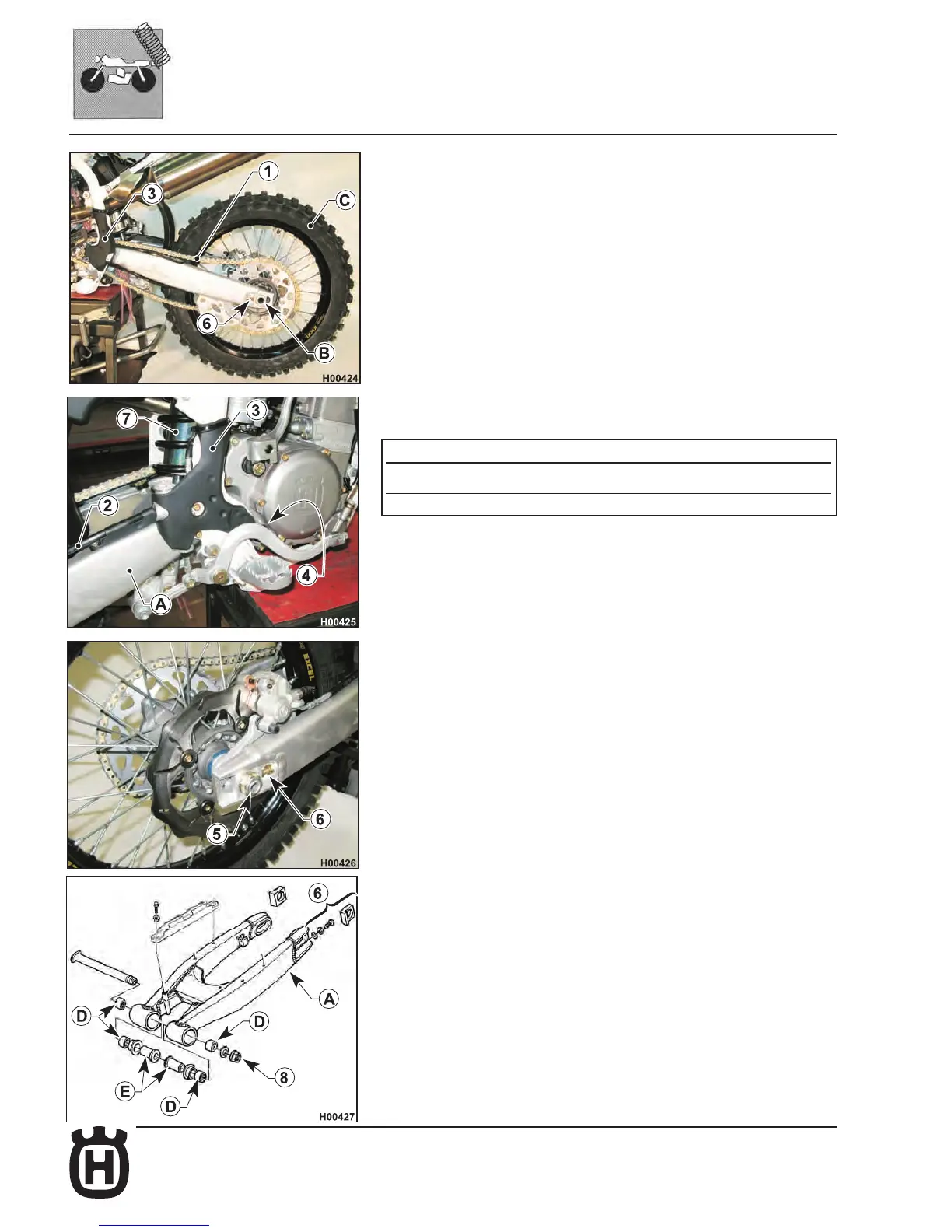
Disassembling and servicing the swinging arm
Set a stand or a block under the engine and see that the rear wheel is lifted from
the ground. Remove the secondary drive chain (1) and detach the rear brake
line (2) from the swinging arm (A). Remove both chassis side guards (3). Dis-
engage the return spring (4) of the rear brake pedal from the chassis. Remove
the wheel axle nut (5) and the wheel axle (B). There is no need to loosen the
chain tensioners (6) on the swinging arm; in this way, the chain tension will re-
main unchanged after reassembly. Extract the complete wheel (C), keeping the
spacers located at the hub sides. Remove the shock absorber (7) as described
at page J.3. Remove the swinging arm shaft nut (8) and then the swinging arm.
Check swinging arm straightness and manually check the roller cages (D) and
their bushings (E) for wear; turn the bushing inside the roller cage: if you feel
any tightness or hear noise, replace them.
TIGHTENING TORQUE FIGURES
5 =142,1 Nm - 14,5 Kgm - 104,81 ft/lb
8 = 122,5 Nm - 12,5 Kgm - 90.3 ft/lb (+LOCTITE 243)
 Loading...