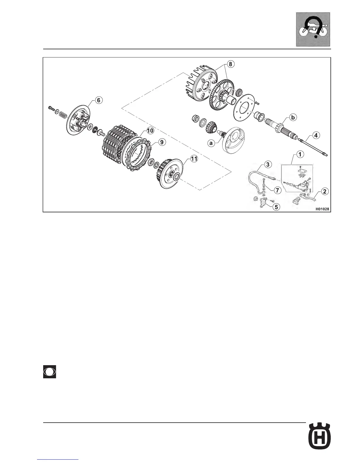
Hydraulic clutch system
The hydraulic circuit is composed of a master cylinder with its reservoir located
on the left side of the handlebar, and a piston installed on the left crankcase
half. The clutch is disengaged by the piston (5) that actuates the pushrod (4)
to operate the pressure plate (6). Drive is transmitted from the crankshaft (a)
to the gearbox input shaft (b) via the gear on the clutch housing (8). The clutch
housing accommodates friction plates (9) and steel plates (10) that operate the
clutch hub (11) secured to the gearbox input shaft.
1 Clutch master cylinder
2 Clutch lever
3 Master cylinder to piston hose
4 Pushrod
5 Piston assembly
6 Pressure plate
7 Bleed tting
8 Clutch housing with clutch ring gear
9 Steel plate
10 Friction plate
11 Clutch hub
a Crankshaft
b Gearbox input shaft
The uid used in the hydraulic circuit will damage painted parts if
spilt on them. Handle it with care when servicing the system.
 Loading...