Page 7.2 - 4 COMBIVERT F5-A, -E, -H © KEB, 2012-10
Analog in- and outputs
7.2.2 Interface selection
7.2.2.1 AN1 / AN2 (An.00, An.10)
Depending on the adjusted interface (An.00 / An.10) the analog inputs AN1 and AN2 can process following
input signals:
An.00 / An.10 = 0 0...±10 V (default)
= 1 0...±20 mA
= 2 4...20 mA
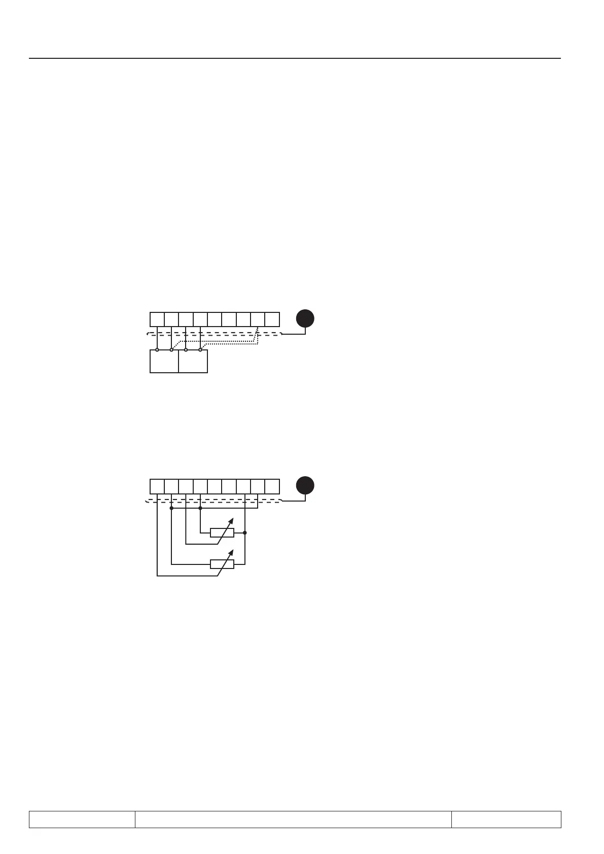
Picture 7.2.2.a Connection as differential voltage inputs 0...±10V DC
Ri = 55 kOhm
X2A.
123456789
PE
0...±10 VDC
+-
SPS
+-
SPS
1)
1) Connect equipotential bonding conductor only, if a potential difference of > 30 V exists between the con-
trols. > 30 V besteht. The internal resistance is reduced to 30 kOhm.
Picture 7.2.2.b Control with potentiometer and internal reference
voltage
X2A.
123456789
R = 3...10 k
PE
0...10V DC Ri=30kΩ (An.00 / An.10 = 0) The output CRF Terminal X2A.7 may be loaded with max. 6mA!
Picture 7.2.2.c Control with current signal (An.00 / An.10 = 1 or 2)
 Loading...


