Speed measurement
© KEB, 2012-10 COMBIVERT F5-A, -E, -H Page 7.11 - 7
7
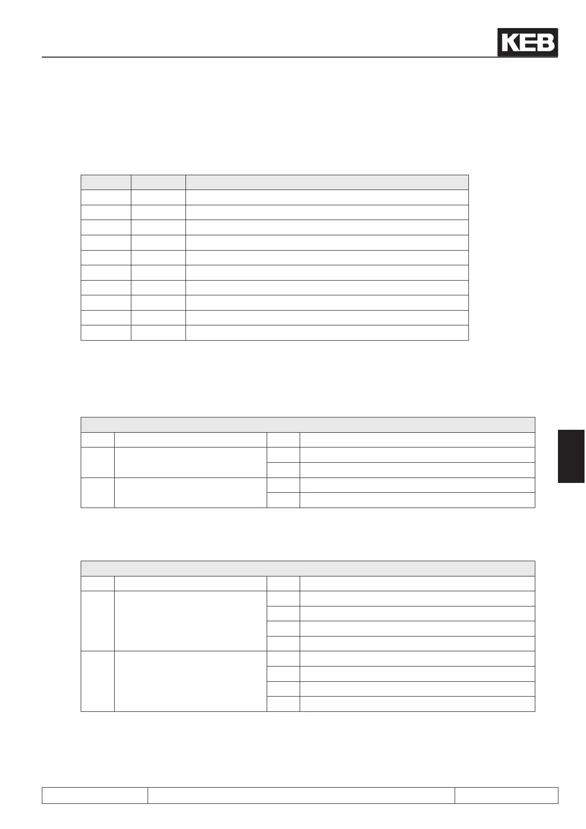
7.11.3.2 Incremental encoder output
The incremental encoder output gives out the signals recorded at the encoder interface 1:1 in RS422-speci-
cation over the second channel (e.g. master drive in synchronous operation).
Signal X4A Description
U
var
5 Supply voltage for encoder (see 7.11.2)
+5,2V 4 Supply voltage for encoder (see 7.11.2)
0 V 9 Reference potential
A 1 Signal input A
_
A 6 Signal input A inverted
B 2 Signal input B
_
B 7 Signal input B inverted
n 3 Reference marking input N
_
N 8 Reference marking input N inverted
Shield housing shielding
Encoder operating mode (Ec.20)
The function of the encoder interfaces is dened with parameter Ec.20.
Ec.20: Encoder operating mode
Bit Description Value Function
1 Channel 2 Function
0 Incremental encoder input
1 Incremental encoder output
2 Terminating resistor at channel 2
0 Input with terminating resistor
2 Input without terminating resistor
Encoder alarm mode (Ec.42)
Parameter Ec.42 denes the alarm function for both encoder.
Ec.42: Encoder alarm mode
Bit Description Value Function
0…1 Alarm channel 1
0 off
1 on
2 on (open-loop)
3 Warning
2…3 Alarm channel 2
0 off
4 on
8 on (open-loop)
12 Warning
 Loading...


