Page 7.5 - 34 COMBIVERT F5-A, -E, -H © KEB, 2012-10
Motor data and controller adjustments of the asynchronous motor
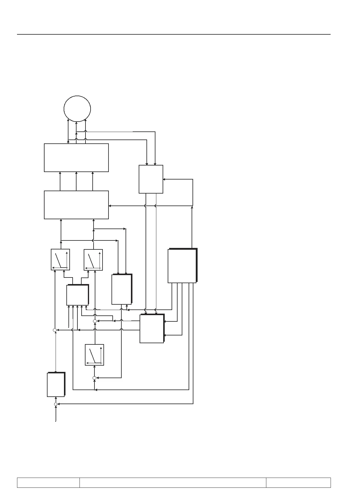
7.5.3 Block diagram
Figure 7.5.3.a Block diagram ASCL
Speed controller
and torque limiting
Transformation
and dead time
compensation
Power unit
Transformation
Motor model,
Tr-adaption and slip
calculation
Selection of the
current feedback
Maximum voltage
controller and eld
weakening
Precontrol and
decoupling
isq controller
isd controller
Usq
Usd
Volt U
Volt V
Volt W
iu
iv
iw
Flux controller
ASM
3ph
ru02
ru07
isq ref
Imr set
Imr
isq reg
isd_ref
isd reg
isq model
isd model
ru.03
ru.87
ru.17
Ec.40
ru.18
Legend block diagram
ru.02
ru.03
ru.07
ru.17
ru.18
ru.87
Ec.40
Ramp output display (speed setpoint)
actual frequency display
Actual value display (actual speed off motor model)
Active current (isq)
actual DC voltage
Magnetisation current (isd)
Actual absolute electrical position
 Loading...


