7.12.2.11 Position reset in the encoder
Reading and the position can be reset to "0" via parameter Ec.38. Value 33 must be entered in parameter Ec.38
to execute the reset. If the reset is successfully completed, parameter Ec.38 is set to 0.
The reset can only be carried out if the encoder / encoder interface supports this function.
This function is supported upto encoder interface software date 11.05.2011.
Only Hiperface encoder are supported.
7.12.3 Synchronous mode
7.12.3.1 Synchronous mode / principle
The synchronous module realises an angle / speed synchronous control of a master drive (control drive) to one
or more slave drives. The control drive must not be closed-loop.
The master position is passed on to the slave. The master must therefore be equipped with an encoder inter-
face with incremental encoder output, and every slave with a second incremental encoder input.
Alternatively, the master can also be operated uncontrolled and the encoder signals of the master drive can be
connected directly to the slave.
The speed ratios are adjustable individually. The gear ratio is adjusted via the numerator / denominator ratio. If the direc-
tions of rotation have to be different, a negative gear ratio has to be set.
For activated position controller, the slave is driven angular-synchronous, for deactivated position controller
(PS.06 = 0), speed-synchronous to the master drive.
The synchronous module contains other variants for synchronisation (constant acceleration ramp or constant
synchronisation path) and a programmable angle adjustment.
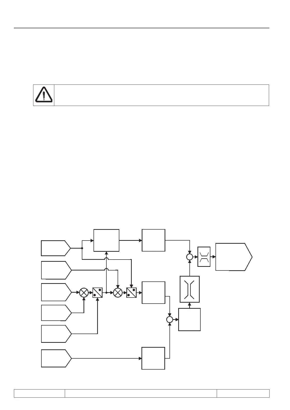
The following mapping shows the general behaviour of synchronous control (without synchronisation phases):
+
+
+
-
Ec.11
encoder
2 (inc/r)
Ec.01
encoder 1
(inc/r)
Increments
of encoder
channel 2
Ec.14
Gear 2 nume-
rator
Ec.15
Gear factor
2 denominator
Increments
of encoder
channel 1
speed
calculation
ru.10
Actual speed
encoder 2
ru.56
Set position
ru.54
actual
position
PS.06 to
PS.08
Position
controller
oP.14/oP.15
absolute
maximum
setpoint
ru.02
display
output display
(setpoint speed for
speed controller
)
PS.09
pos
Posi/synchronous
Page 7.12 - 14 COMBIVERT F5-A, -E, -H © KEB, 2012-10
Posi- and synchronous operating
 Loading...


