Motor data and controller adjustments of the synchronous motor
© KEB, 2012-10 COMBIVERT F5-A, -E, -H Page 7.6 - 5
7
7.6.1.4 Motor adaption
Fr.10 = 2 (for some applications Fr.10 = 1 /explanation see below) must be entered once after input of the motor
data.
The parameter can only be written in „nop“ status !
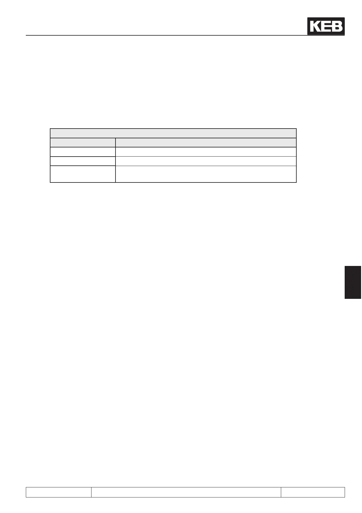
Fr.10 load motor dependent parameter
Value Function
0: nished
1: uF.09 Calculation depending on uF.09 respectively voltage class
2: actual DC link
voltage
Calculation depending on act. DC link voltage
The calculation at Fr.10 = 1 is depending on the voltage entered in parameter uF.09 "Voltage stabilisation". If
this parameter displays "off" (standard adjustment), then the voltage class of the frequency inverter (400V or
230V) is used.
The current DC link voltage of the frequency inverter, which is proportional to the supply input voltage, is con-
sidered for the calculations at Fr.10 = 2.
However this only applies uF.09 is on "off".
Thus the following parameter are pre-charged dependent on the motor and inverter data:
Current controller
- dS.00 Kp current
- dS.01 Ki current
Torque limits:
- cS.19 Absolute torque reference
- cS.20...23 Torque limits clockwise- counter clockwise rotation/ motoring- generating
- Pn.61 Abnormal stopping torque limit
- dr.33 DSM max. torque
Motor type (only at SCL):
- nn.01 Stabilisation current
- nn.02 lower speed limit / stabilisation
- nn.03 upper speed limit / stabilisation
- nn.10 Standstill current
- nn.11 Type stabilization time constant
 Loading...


