Analog in- and outputs
© KEB, 2012-10 COMBIVERT F5-A, -E, -H Page 7.2 - 5
7
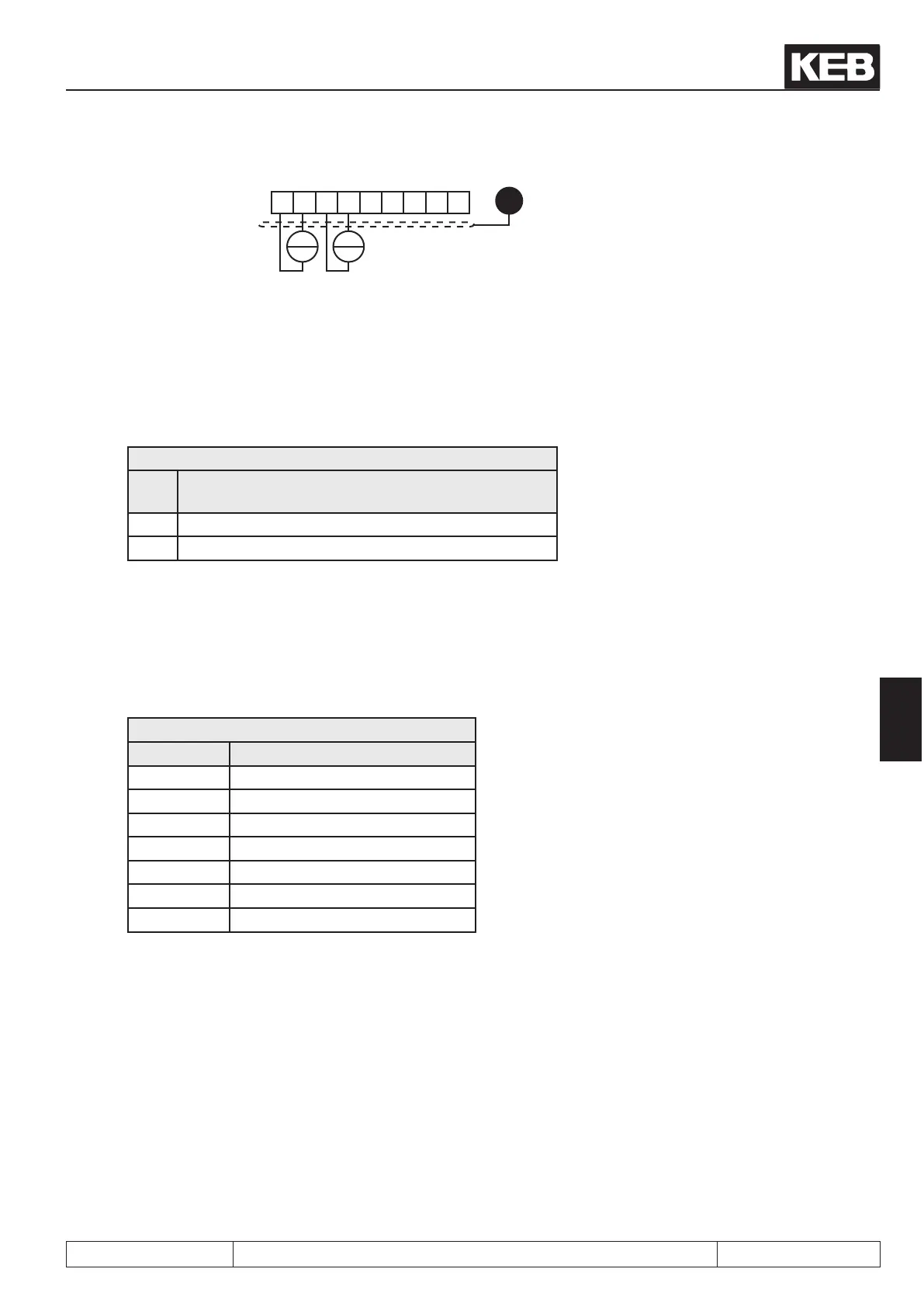
X2A.
123456789
+
0...±20 mADC
4...20 mADC
Ri = 250 Ω
PE
+
7.2.2.2 AN3 (An.20)
With An.20 it is determined from where the 3. analog input value is received. Following values can be dened:
An.20: AN3
Va-
lue
Function
0 Analog option (AN3)
1 Analog input 1 (AN1)
7.2.3 Noiselter(An.01,An.11, An.21)
The noise lters shall suppress disturbances and ripples of the input signals. If the noise lter is switched off the
analog inputs are queried every 1 ms and the recorded value is transferred then. The noise lter adjustments
preset the number of sampled values for the averaging.
An.01/11/21:Noiselter
Value Function
0 off (no averaging)
1 double
2 4-fold
3 8-fold
4 16-fold
5 32-fold
6 64-fold
7.2.4 Save mode (An.02, An.12, An.22)
Coming from the input lter the save mode can be switched on with An.02 / An.12 / An.22 . If now the pro-
grammable digital input (value 1) is set the analog signal is processed directly and written parallel into the non-
volatile memory. As soon as the digital input is disconnected (value 0), the inverter continuos to run with value
stored in the memory. Moreover, with An.02/ An.12/ An.22 it can be determined whether the memory contents
are saved or deleted upon switch off.
 Loading...


