Page 7.11 - 4 COMBIVERT F5-A, -E, -H © KEB, 2012-10
Speed measurement
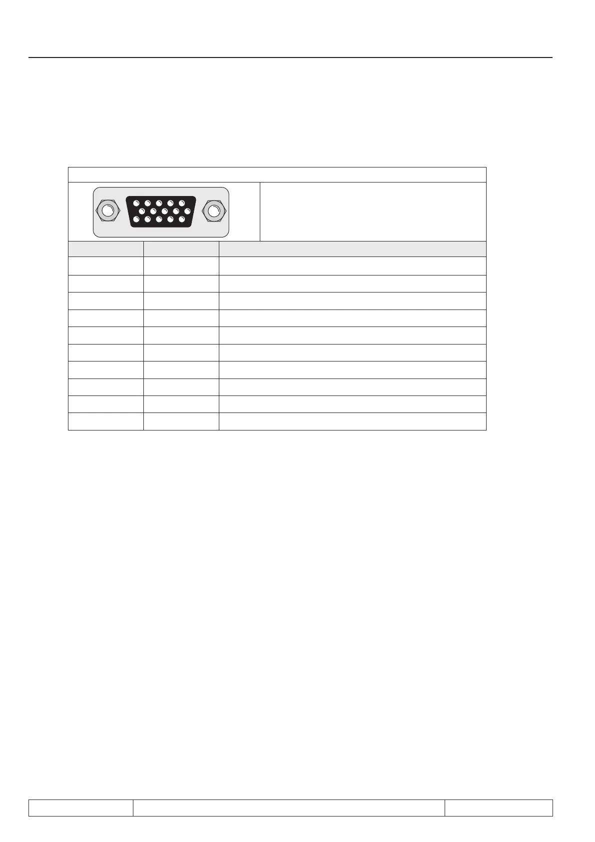
7.11.2 Encoder interface channel 1 (X3A)
7.11.2.1 TTL incremental encoder input (standard at F5-M)
Fig. 7.11.2 Encoder interface channel 1 (X3A)
5432 1
10 9876
15 14 13 12 11
Only when the inverter is switched off and the
voltage supply is disconnected may the plug
be pulled out or plugged in !
Signal X3A Description
U
var
11 Supply voltage for encoder
+5 V 12 Supply voltage for encoder
0 V 13 Reference potential
A 8 Signal input A
_
A 3 Signal input A inverted
B 9 Signal input B
4 Signal input B inverted
n 15 Reference marking input N
14 Reference marking input N inverted
Shield housing shielding
Following specications apply to the encoder
interface 1 (X3A):
- Limiting frequency of input fG = 300 kHz
- internal terminating resistor Rt = 150 ohm
- 2…5 V High level at rectangular signals
Inputs
The signal and reference marking inputs can be triggered with rectangular pulses. The signal inputs must ge-
nerally be connected. The reference marking signals are only needed for the reference point approach in the
positioning operation (F5M/S).
For encoder inputs with HTL level please contact KEB!
 Loading...


