Digital in- and outputs
© KEB, 2012-10 COMBIVERT F5-A, -E, -H Page 7.3 - 41
7
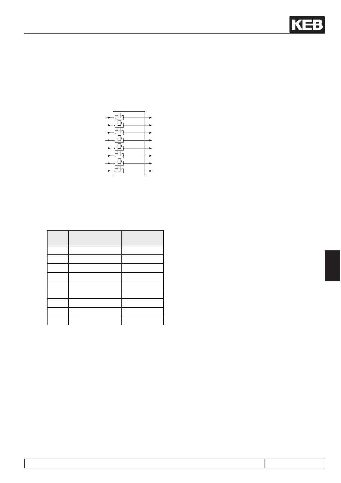
As shown in Fig. 7.3.23b, the outputs can be inverted again after linking with parameter do.42. The parameter is
bit-coded, i.e. according to following table the value belonging to this output must be entered. If several outputs
shall be inverted, the sum is to be formed.
Fig. 7.3.23b. Inversion of Outputs
1
1
1
1
do.42
Bit 0
Bit 1
Bit 2
Bit 3
Bit 4
Bit 5
Bit 6
Bit 7
1
2
4
8
16
32
64
128
1
1
1
1
do.41
7.3.24 Output terminal state (ru.25) and digital output state (ru.80)
Parameter ru.25 displays the logic condition of the digital outputs after the allocation by do.51. Parameter ru.80
displays the logic condition before the allocation. If an output is setthe appropriate decimal value according to
the table below, is output. If several outputs are set, then the sum of the decimal values is output.
Name Function Decimal va-
lues
– no output 0
O1 Transistor output 1
O2 Transistor output 2
R1 Relay output 4
R2 Relay output 8
OA Internal output 16
OB Internal output 32
OC Internal output 64
OD Internal output 128
 Loading...


