Analog in- and outputs
© KEB, 2012-10 COMBIVERT F5-A, -E, -H Page 7.2 - 3
7
7.2 Analog in- and outputs
7.2.1 Brief description analog inputs
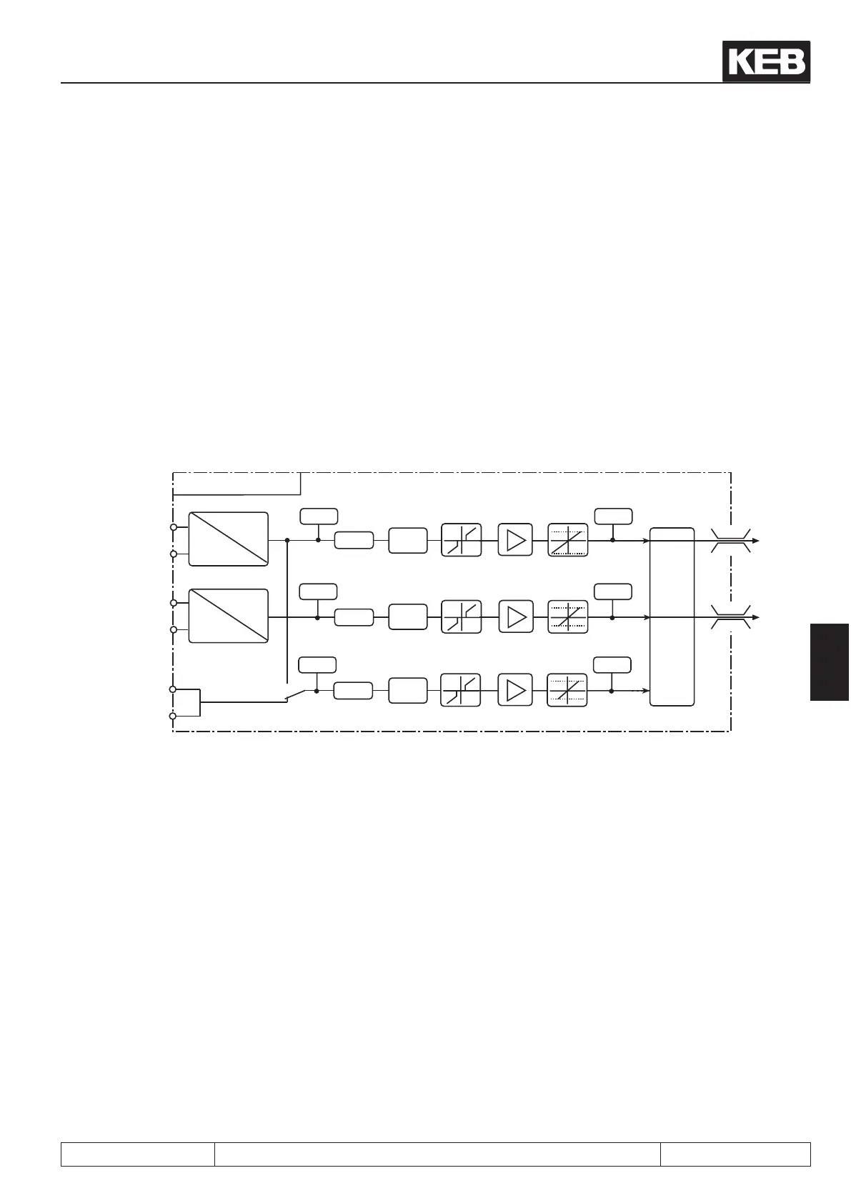
By selecting an input interface (An.00/ 10) input AN1 or AN2 can be adjusted to the applied input signal. By
An.20 the third analog input can be switched additionally to AN1. Subsequently the analog inputs are smoothed
in an electronic lter (An.01/ 11/ 21) by averaging. A save mode can be adjusted with An.02/12/22 and activated
with a programmable input (An.03/13/23). To avoid voltage uctuations and ripple voltages around the zero
point the analog signal can be faded out around the zero point up to ±10 % (An.04/14/24). In the characteristic
amplier the input signals can be inuenced in X and Y direction as well as in the rise (An.05...07/ 15...17/
25...27). At the output of the characteristic amplier the signal can be limited to minimum and maximum value
(An.08, 09/18, 19/28, 29). At the output of the block it can be dened with An.30 which analog signal serves
as reference value and which one serves as auxiliary value. The ru-Parameters are used for the display of the
analog signal pre and post amplier. The internal values are limited to ±400%.
Picture 7.2.1 Principle of the analog inputs
+AN1 (X2A.1)
-AN1 (X2A.2)
+AN2 (X2A.3)
-AN2 (X2A.4)
+AN3 (opt.)
-AN3 (opt.)
400%
-400%
400%
-400%
An.18
An.19
An.1
An.11
An.4
An.14
ru.29
An.10
An.5
An.6
An.7
An.15
An.16
An.17
An.8
An.9
ru.30
An.30
ru.27 ru.28
0...±100%
An.0
0...±100%
±10V
0...±20mA
4...20mA
±10V
0...±20mA
4...20mA
An.28
An.29
An.21
An.24
ru.31
An.25
An.26
An.27
ru.32
An.20
An.12
An.13
An.2
An.3
An.22
An.23
Analog inputs
REF
AUX
An.00
An.01
An.02
An.03
An.04
An.05
An.06
An.07
An.08
An.09
An.10
An.11
An.12
An.13
An.14
An.15
An.16
An.17
An.18
AN1 interface selection
AN1 interference suppression lter
AN1 save mode
AN1 save mode input selection
AN1 Nullzero point hysteresis
AN1 amplication
AN1 offset X
AN1 offset Y
AN1 lower limit
AN1 upper limit
AN2 interface selection
AN2 interference suppression lter
AN2 save mode
AN2 input selection
AN2 zero point hysteresis
AN2 amplication
AN2 offset X
AN2 offset Y
AN2 lower limit
An.19
An.20
An.21
An.22
An.23
An.24
An.25
An.26
An.27
An.28
An.29
An.30
ru.27
ru.28
ru.29
ru.30
ru.31
ru.32
AN2 upper limit
AN3 interface selection
AN3 interference suppression lter
AN3 save mode
AN3 input selection
AN3 zero point hysteresis
AN3 amplication
AN3 offset X
AN3 offset Y
AN3 lower limit
AN3 upper limit
Selection Set Point-/Auxiliary Input AUX-
Function
AN1 pre amplier display
AN1 post amplier display
AN2 pre amplier display
AN2 post amplier display
AN3 pre amplier display
AN3 post amplier display
 Loading...


