Digital in- and outputs
© KEB, 2012-10 COMBIVERT F5-A, -E, -H Page 7.3 - 39
7
With parameters do.08...do.15 each of the 8 switching conditions (do.00...do.07) can be inverted separately
for each ag. With this function it is possible to set any chosen switching condition as non-condition. The pa-
rameter is bit-coded. According to Fig. 7.3.15 theweighting for the switching conditions to be inverted must be
entered in do.08...do.15. If several conditions shall be inverted, the sum is to be formed.
Example:
Output X2A.19 shall be set when the inverter is not accelerating! In this case we assign the switching condition
21 (inverter accelerates) for example to do.01 (enter value 21). We invert the switching condition (do.01) with
do.09, so enter value „2“.
7.3.19Selectionofswitchingconditionsforags0...7(do.16...do.23)
Parameters do.16...do.23 serve for the selection of the 8 preassigned switching conditions. The selection is
done foreach ag separately, where one can choose between no one and up to all 8 switching conditions. The
value of the selected switching condition must be entered in do.16...do.23 in accordance with g. 7.3.15 . If
several conditions shall be inverted, the sum is to be formed.
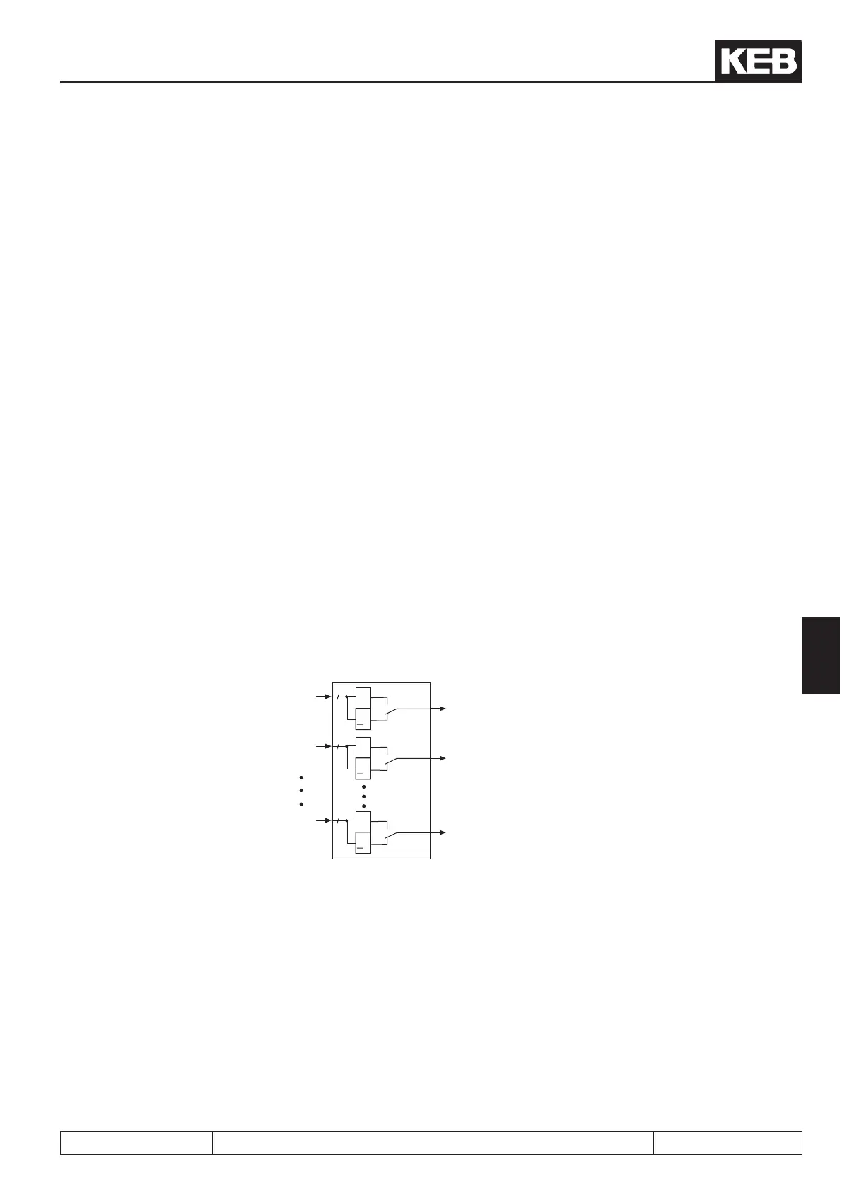
7.3.20 AND/OR connections of the switching conditions (do.24)
After the switching conditons are selected for each output, it can now be determined, how these are connected.
As a default all conditions are OR connected, i.e. the ag is set if one of the selected conditions is fullled.
Another possibility is the AND connection which can be adjusted with do.24. AND connection means that all
selected conditions must be fullled before the ag is set.
Parameter do.24 is bit-coded. The table under 7.3.17 shows the assignment.
Fig. 7.3.20 Linking the switching conditions in logic step 1
&
>
1
0
1
Bit 0
8
do.16
&
>
1
0
1
Bit 1
8
do.17
&
>
1
0
1
Bit 7
8
do.23
do.24
Flag 0
Flag 1
Flag 7
 Loading...


