Page 7.8 - 6 COMBIVERT F5-A, -E, -H © KEB, 2012-10
Torque display and -limiting
The value for dr.16 can be higher than the value in dr.15, since the breakdown torque of the motor can be higher
than the maximum torque of the inverter.
The safety reserve is necessary because the limiting characteristic must be sufciently far from the physical
breakdown torque of the motor.
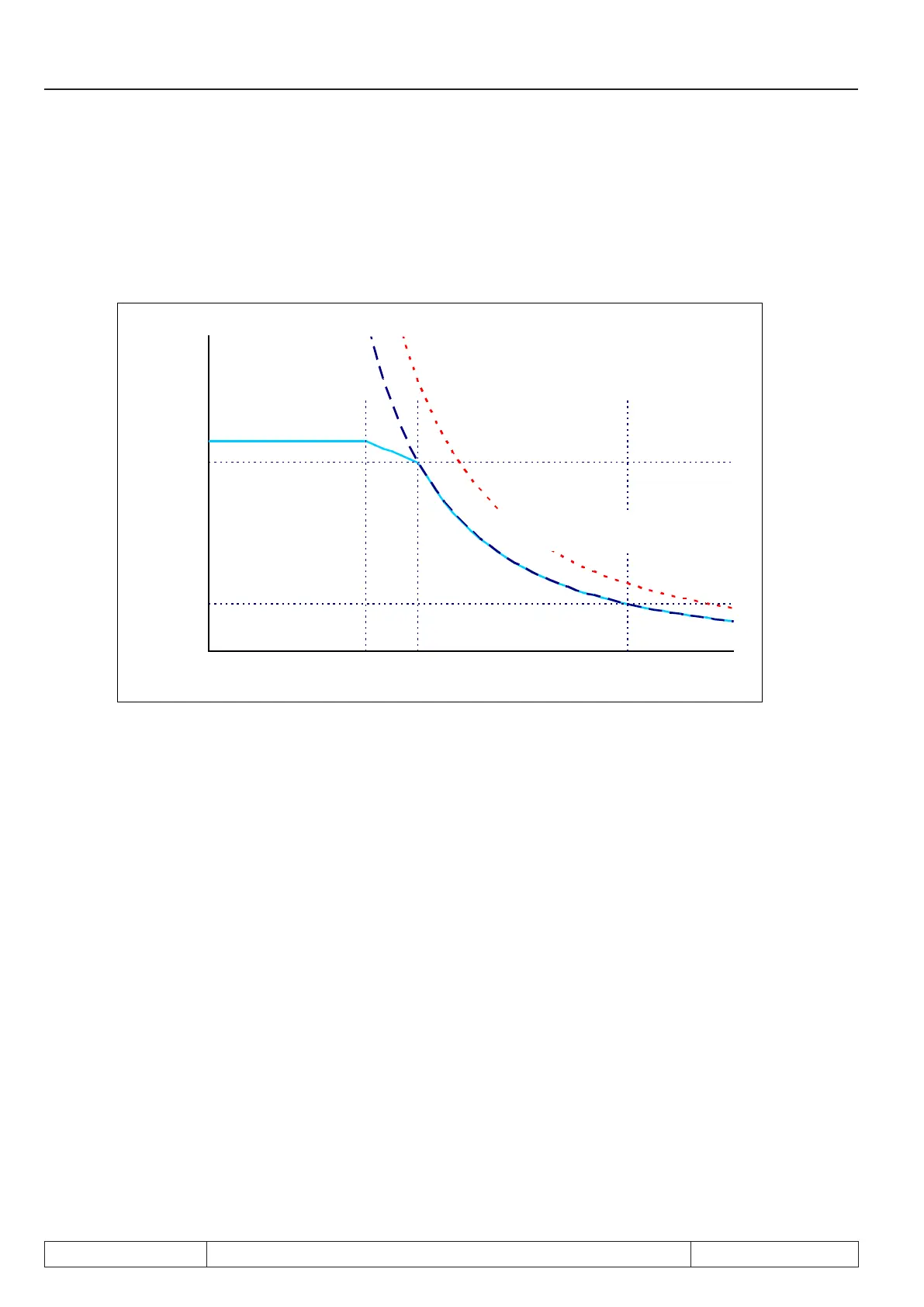
Picture 7.8.2.2 b Field weakening range square reduction
quadratische Absenkung
ds.03 "Felschwächkennlinie" = 1: ein
quadratische Kippmomentkennlinie
des Motors
7.8.3 Physical torque limits DSM
7.8.3.1 Torque limits in base speed range (dr.27, dr.15)
The rated torque of the synchronous motor must be entered according to the name plate in parameter dr.27.
The maximum torque (limited by the maximum current of the inverter) is displayed in dr.15.
At activated hardware current limit (uF.15 = 1 or 2) the maximum current is equal to the hardware current level
(In.18) less safety reserve of 5% of the inverter rated current.
At deactivated hardware current limit (uF.15 = 0) the maximum current is equal to the overcurrent error limit less
safety reserve of 10%.
7.8.3.2 Torque limits in base speed range
Normally a synchronous motor is operated with a magnetization current of 0.
If the usable speed range shall be increased, drive into the "eld weakening range". In this range, the maxi-
mum voltage controller provides a magnetising current that counteracts the pulse wheel voltage. If the inverter
changes to error, the magnetizing current is = 0. Then the motor refeeds the pulse wheel voltage into the in-
verter. This voltage may maximally reach the overvoltage threshold, because otherwise the inverter is dama-
ged. Therefore the permissible speed is limited. If the drive exceeds the value of parameter ru.79 "abs. speed
(EMC)" the inverter changes into "Error! overspeed“.
 Loading...


