Rotary table
range
ru.56: Set position
ru.02: ramp output display (set-
point speed controller)
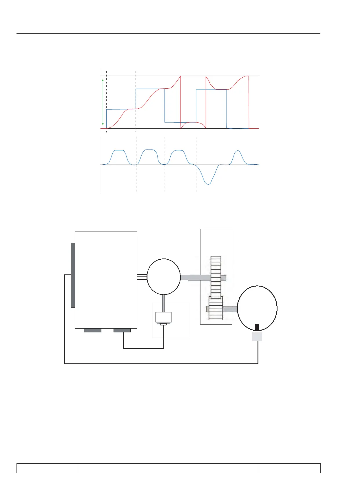
7.12.4.10.2 Rotary table without path optimization
inverter
control terminal block X2A
X3B
Encoder
channel 2
X3A
Encoder
channel1
F5A-S
or
F5A-M
M
3~
Incremental
encoder
Gear
Rotary
table
Initiator
This mode is particularly suitable for round table applications where only one encoder is used for the motor po-
sition. The gear between the motor and the round table can cause the position of the round table to be different
for identical motor positions, depending on the direction of rotation from which the position was approached.
To avoid these problem for applications where the gear backlash cannot be ignored, the target must always
be approached from the same direction of rotation. The direction from which a position is approached is deter-
mined by the sign of PS.24 "index / position": Positive values mean the position is approached from the right,
negative values lead to an approach from the left.
Page 7.12 - 54 COMBIVERT F5-A, -E, -H © KEB, 2012-10
Posi- and synchronous operating
 Loading...


