Page 7.2 - 14 COMBIVERT F5-A, -E, -H © KEB, 2012-10
Analog in- and outputs
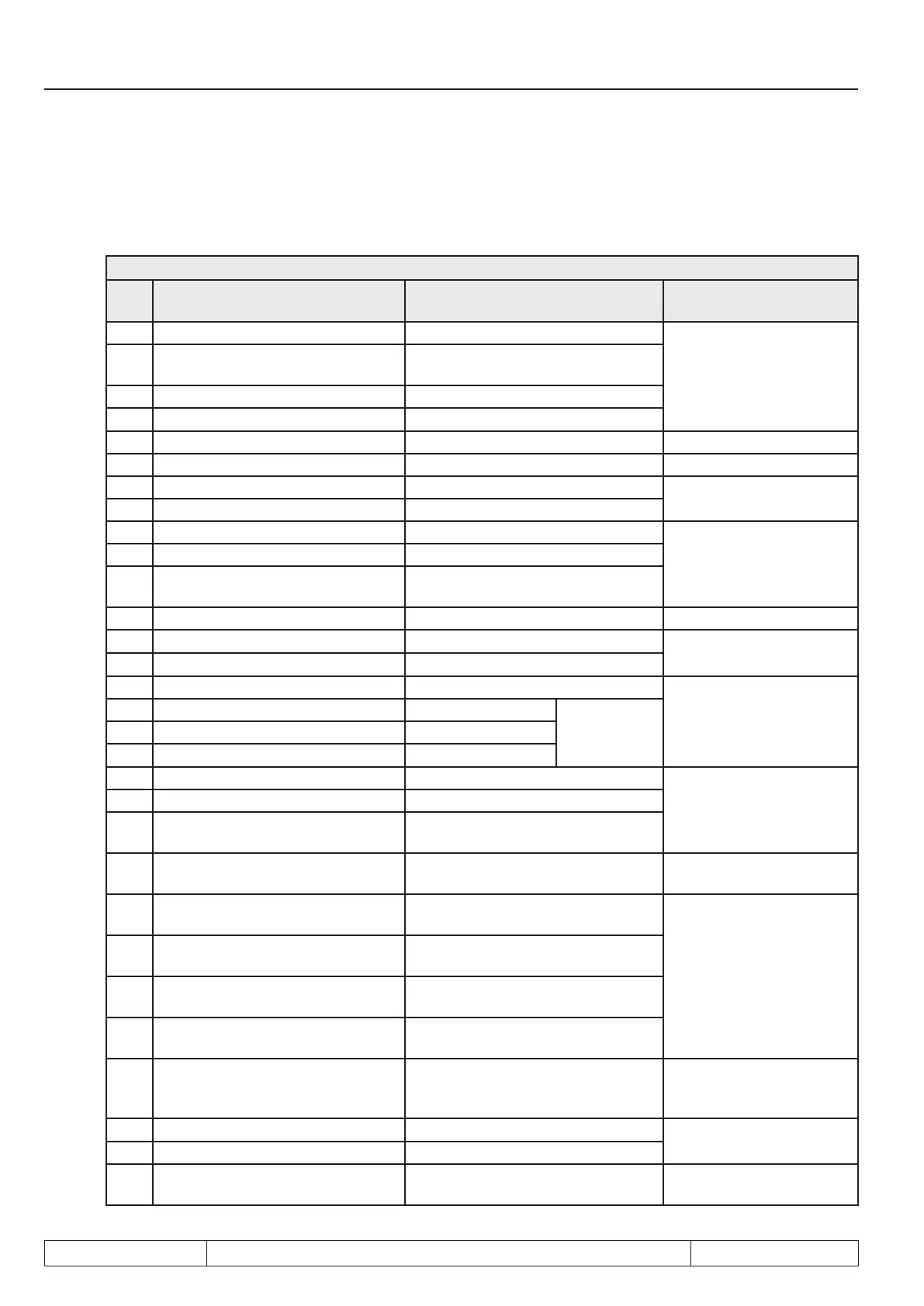
7.2.12 ANOUT 1 / -2 / -3 / -4 / function (An.31 / An.36 / An.41, An.47)
These parameters dene the function which controls the respective output . Following adjustments are possi-
ble:
An.31/ An.36/ An.41/ An.47
Va-
lue
Function Output of
100 % corresponds to
0 Absolute actual value ru.07 Amount of the speed actual value
3000 rpm
2)
1 Absolute set value ru.01
Amount of speed set value before ramp
generator
2 Actual value ru.07 Speed actual value
3 Set value ru.01 Speed set value
4 Output voltage ru.20 Output voltage
0...500 V
5 DC voltage ru.18 actual DC voltage 0...1000 V
6 Apparent current ru.15 apparent current
0...2 x inverter current (In.01)
7 Active current ru.17 active current
8 Digital setting with An.32/ 37/ 42/ 48 with An.32/ 37/ 42/ 48 preset value
0...100 %
9 External PID output ru.52 Output value of the PID controller
10 Absolute ext. PIDoutput ru.52
Amount of the PID controller output va-
lue
11 Absolute active current ru.17 Amount of the active current 0...2 x inverter current (In.01)
12 Heat sink temperature ru.38 Power module temperature
0...100 °C
13 Motor temperature ru.46 Motor temperature
14 Actual torque (F5-M/S) Actual torque
0...3 x rated torque
DASM: dr.14
DSM: dr.27
15 Absolute actual torque (F5-M/S) Amount actual torque
only in closed-
loop operation
16 Set torque (F5-M/S) Set torque
17 Absolute set torque (F5-M/S) Amount set torque
18
system deviation of the speed controller
system deviation of the speed controller
0...3000 rpm
19 Speed reference variable ru.02 Speed set value after ramp generator
20
Absolute speed reference variable
ru.02
Angle difference
21 Angle difference (ru.58) Angle difference
0... number of increments for
a revolution
22
Analog input 1 pre amplier display
(ru.27)
Value of AN.01 at terminal
0...100 %
23
Analog input 1 post amplier display
(ru.28)
Value of AN.01 after analog value pro-
cessing
24
Analog input 2 pre amplier display
(ru.29)
Value of AN.02 at terminal
25
Analog input 2 post amplier display
(ru.30)
Value of AN.02 after analog value pro-
cessing
26 Active power (ru.81) Active power
0...2 x rated motor power
DASM: dr.03
DSM: dr.32
27 Actual position (ru.54) Actual position
Ref-position 0 % (PS.41)
Ref-position 100 % (PS.42)
28 Set position (ru.56) Set position
29 Max. torque in % (ru.90)
act. torque, referring to the max. permis-
sible torque of the drive chain
0...100 %
1)
dependent on the inverter rated current (In.1),
2)
dependent on ud.2,
3)
dependent on the motor
 Loading...


