Operating and appliance data
© KEB, 2012-10 COMBIVERT F5-A, -E, -H Page 7.1 - 3
7
7. Functions
7.1 Operating and appliance data
The parameter groups „ru“, „In“ and „SY“ are described in this chapter. They serve for the operational monito-
ring, error analysis and evaluation as well as for the unit identication.
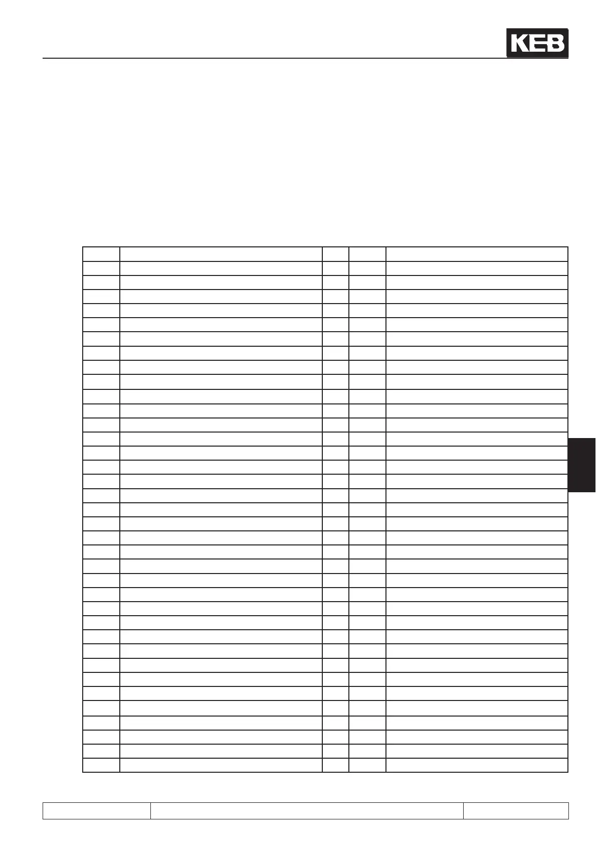
7.1.1 Overview of the ru-Parameters
The ru- (run) parameter group represents the multimeter of the inverter. Here speeds, currents, voltages etc.
are displayed, with those a statement about the operating condition of the inverter can be made. Especially du-
ring start-up or trouble shooting on a unit, this can turn out to be a great aid. Following parameters are available:
ru.00 inverter state ru.41 modulation on counter
ru.01 set value display ru.42 modulation grade
ru.02 ramp output display ru.43 timer 1 display
ru.03 actual frequency display ru.44 timer 2 display
ru.07 Actual value display ru.45 act. switching frequency
ru.09 encoder 1 speed ru.46 motor temperature
ru.10 encoder 2 speed ru.47 act. torque limit mot.
ru.11 set torque display ru.48 act. torque limit gen.
ru.12 actual torque display ru.49 actual ref. torque
ru.13 actual utilization ru.51 heat sink temperaure
ru.14 peak utilization ru.52 ext. PID out display
ru.15 apparent current ru.53 AUX display
ru.16 peak apparent current ru.54 actual position
ru.17 active current ru.56 set position
ru.18 actual DC voltage ru.58 angle difference
ru.19 peak DC voltage ru.59 rotor adaption factor
ru.20 output voltage ru.60 Act. position index
ru.21 Terminal Status ru.61 target position
ru.22 internal input state ru.63 prole speed
ru.23 output condition state ru.68 rated DC voltage
ru.24 State of output ags ru.69 Distance reference point to zero signal
ru.25 output terminal state ru.71 Teach position
ru.26 Active parameter set ru.73 set torque in percent
ru.27 AN1 pre amplier display ru.74 Act. torque in percent
ru.28 AN1 post amplier display ru.78 act. val. display in percent
ru.29 AN2 pre amplier display ru.79 Abs. speed value (EMK)
ru.30 AN2 post amplier display ru.80 digital output state
ru.31 AN3 pre amplier display ru.81 active power
ru.32 AN3 post amplier display ru.82 Ramp val. display high-resolution
ru.33 ANOUT1 pre ampl. display
ru.83 Actual val. display high-resolution
ru.34 ANOUT1 post ampl.display
ru.84 accessible rel. position
ru.35 ANOUT2 pre ampl. display ru.85 Peak encoder 1 speed
ru.36 ANOUT2 post ampl. display ru.86 Peak encoder 2 speed
ru.37 motorpoti actual value ru.87 Magnetizing current
ru.38 power module temperature ru.89 actual source speed
ru.39 Overload integrator (E.OL) ru.90 Max. torque in percent
ru.40 power on counter
 Loading...


