Current control, -limiting and switching frequencies
© KEB, 2012-10 COMBIVERT F5-A, -E, -H Page 7.10 - 5
7
7.10.3 Switching frequencies and derating
7.10.3.1 Switching frequency (uF.11, In.03, In.04, ru.45)
The desired switching frequency can be selected in parameter uF.11. The higher the switching frequency the
smaller the noise level and the smaller the current ripple and the losses in the motor involved. Simultaneously
the losses in the inverter and also the isolation straining of the motor increase caused by switching edges.
uF.11: Switching frequency
Value Switching frequency
0 2 kHz
1 4 kHz
2 8 kHz
3 12 kHz
4
16 kHz
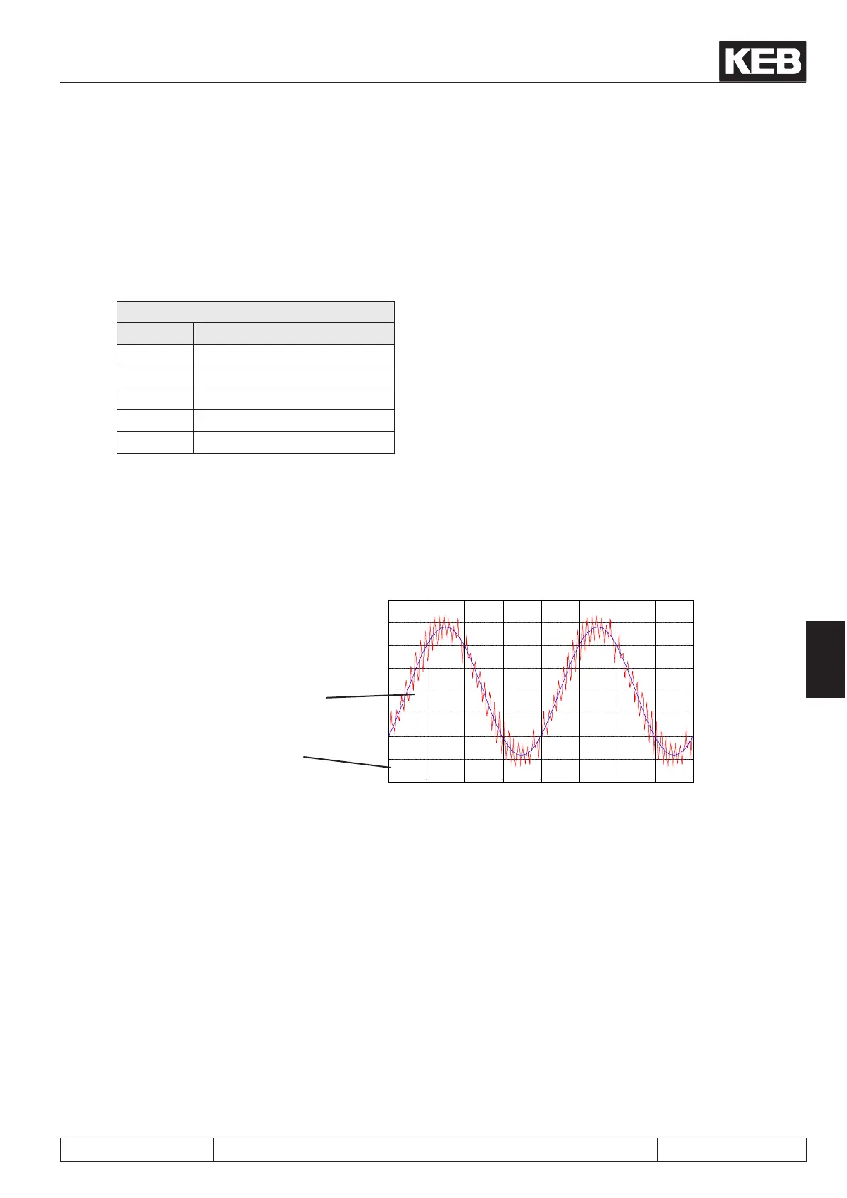
The current ripple is a harmonic current which superimposes the sine-wave output current.
It is generated by the clocked output voltage of the frequency inverter. This ripple increases the maximum value
of the current and thus may lead to triggering of the overcurrent error or the hardware current limit, although the
displayed apparent current (ru.15) or utilization value (ru.13) is signicant below this limit.
Picture 7.10.3.1 Carrier frequencies
Base frequency of the phase
current
actual current = base frequency
with superimposed ripple
0.0955 0.096 0.0965 0.097 0.0975 0.098 0.0985 0.099 0.0995
-20
-15
-10
-5
0
5
10
15
20
The size of the current ripple is depending on the switching frequency and the motor inductance. The current
ripple is usually insignicant for standard motors with a power < 50kW and a rated switching frequency of the
unit of min. 4 kHz.
The smaller the leakage inductance (ASM) and/or the winding inductance (SM) the higher the ripple. This is
particularly the case for motors with high power or spindle motors. Therefore the carrier frequency must be
selected as high as possible for these motors.
Attention: Generally the switching frequency should be at least 10 times higher than the maximum occurring
output frequency of the inverter.
The maximum switching frequency can be read in parameter In.03. The frequency inverter can be operated
permanently only with its rated carrier frequency (In.04) (independent on temperature and utilization).
 Loading...


