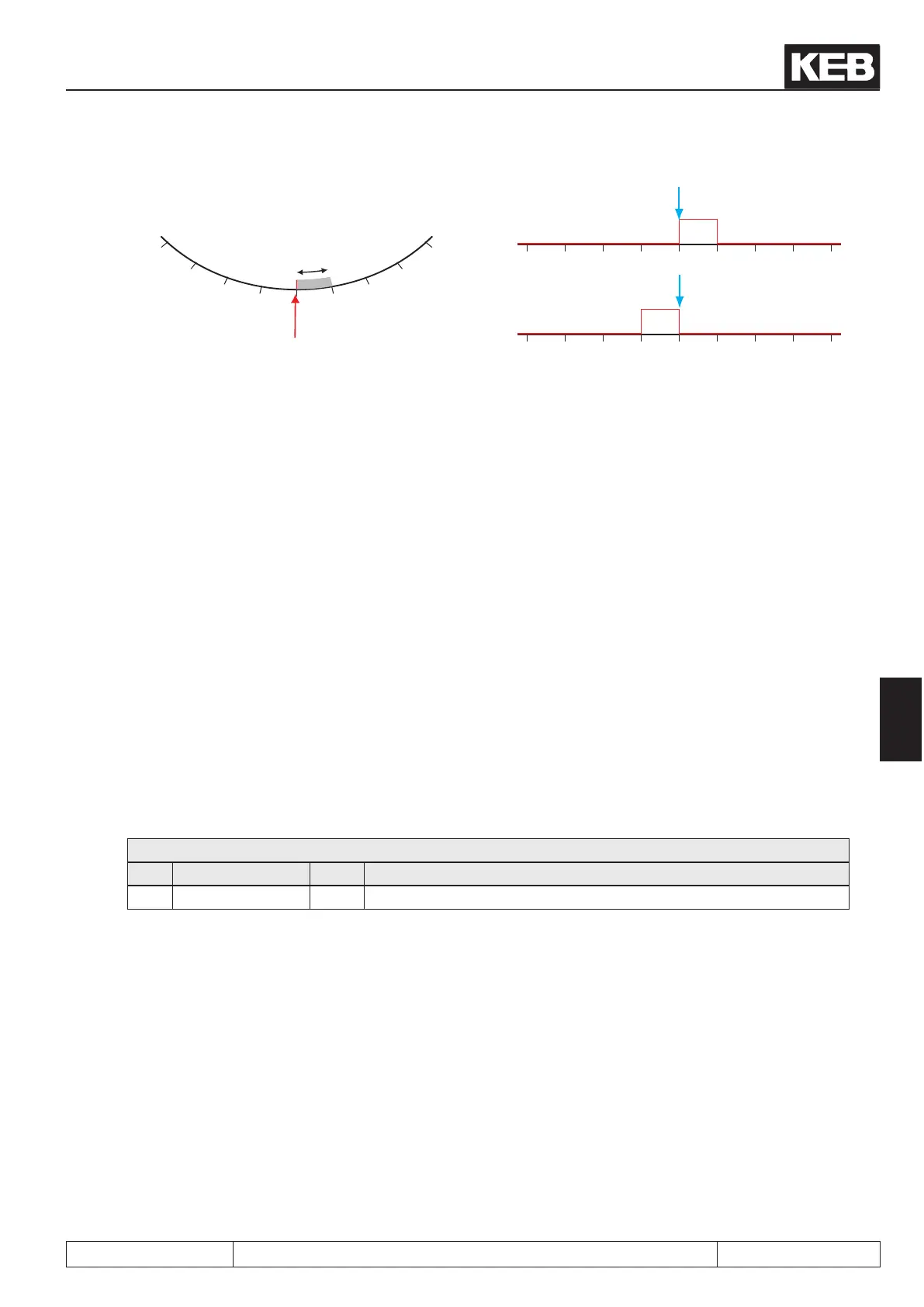
reverse
forward
Initiatior signal
Initiatior signal
correction
correction
Initiatior
signal
Correction point
3000
3000
4000
4000
5000
5000
6000
6000
7000
7000
3000
4000
5000
6000
7000
Rotary table
An important point for ying referencing is the suppression of interference pulses that can trigger a referencing
at the wrong position.
Basic requirement is the EMC conform installation. The programming of a digital lter in the di-parameters is
unsuitable for the ying referencing since the time delay caused by the lter distorts the referencing.
Therefore, there is the parameter PS.40 "reference point window". Only an initiator pulse within the position
window of +/- PS.40 around the reference point PS.17 triggers an adjustment.
Example:
PS.17 = 5000 increments / PS.40 = 500
Then, referencing signals are accepted only if the actual position ru.54 is in the range of 4500 to 5500.
The default value for PS.40 is 0, i.e., the interference suppression is switched off.
To receive a warning that interference pulses have occurred, a digital output can be set if a referencing signal
occurs outside of the permitted window.
For this, value78 „totary table reference invalid“ must be selected as switching condition in the do-parameters.The
switching condition is reset with the next "start position" command and after overdriving the reference switch.
7.12.4.11 Posimode/denedstop
In some applications, a drive shall stop within one revolution at a dened position during vector controlled ope-
ration. For such applications, the mode "position specication relative to the null signal" was created.
PS.27: Index mode
Bit Meaning Value Explanation
1...3 Position setting 4 Relative to zero signal
In this application, the functions "position / synchronous activation" and "start positioning" are connected to the
same input. If the signal at this input is not active, the drive runs vector controlled.
If the input is activated, the drive correspondingly delays the dened acceleration-, deceleration- and S-curve-
times. Thereby, it positions to the distance to the marker pulse dened in PS.24. How many revolutions it still
travels during the delay dependent on the speed and the adjusted ramps. Only the position within one revolu-
tion of the position encoder at which the drive stops is dened.
Only values from 0 to encoder (inc/r) * 2 enc. trigger may be preset in this mode in PS.24 „index/ position“.
The direction of rotation from which the position is approached is always the direction of rotation of the drive
before activation of the positioning.
Attention: If the modulation is switched off (switch-off the control release, error) while the drive rests at the stop-
ping position, the drive will be in speed-controlled operation again after switching on the modulation.
Posi- and synchronous operating
© KEB, 2012-10 COMBIVERT F5-A, -E, -H Page 7.12 - 57
7
 Loading...


