+
+
+
-
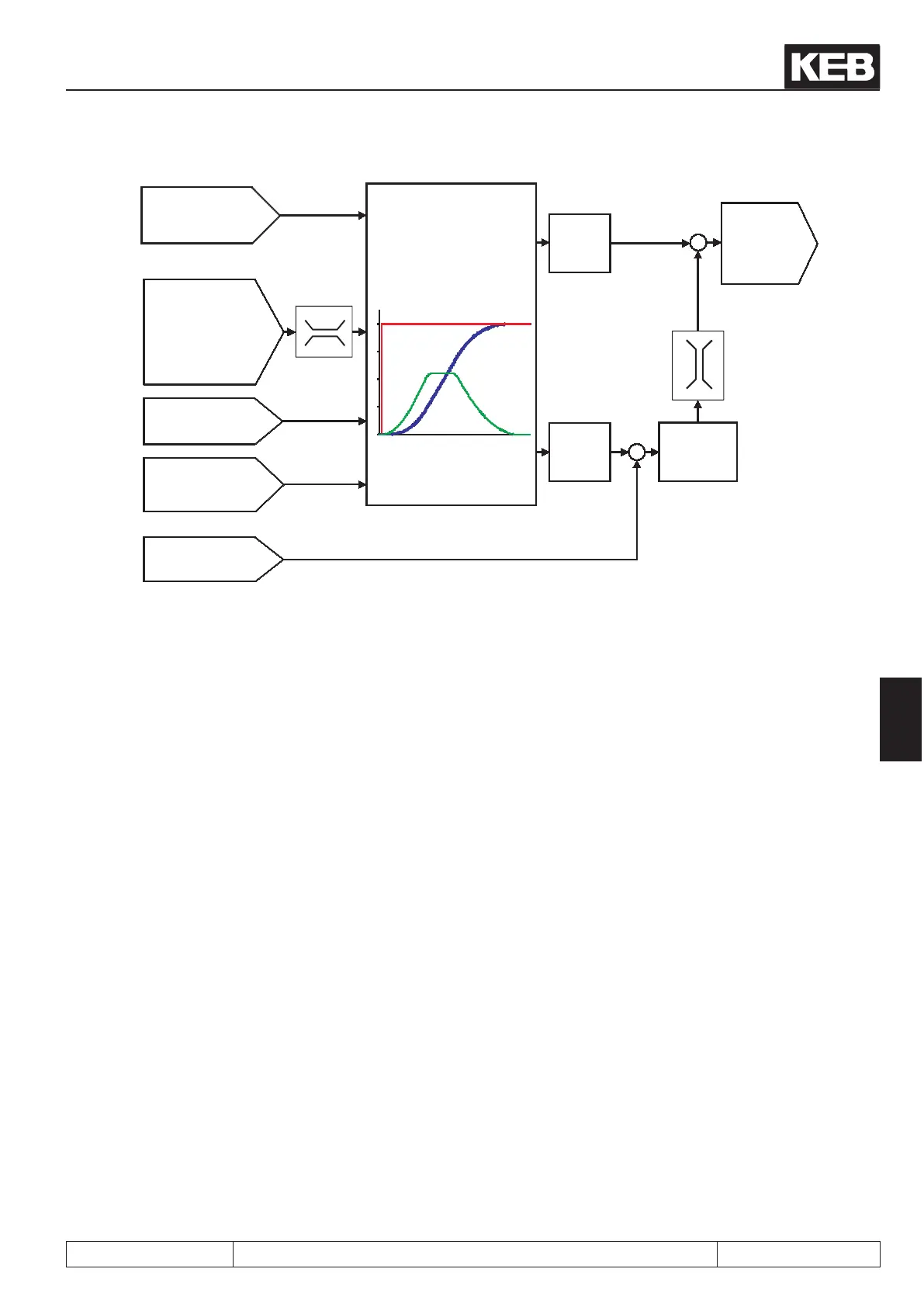
PS.24
index / position
(=ru.61) target position
PS.25
Index / speed
in % of oP.10
oP.28..31
Acceleration /
deceleration time
oP.32..35 and oP.70..73
S-curve times
(jerk limitation)
ru.54
actual position
oP.14
abs. max. reference
forward
Prolecalculation
ru.61: target position [Inc]
ru.56: set position [Inc]
prole speed [rpm]
Prole
speed
PS.09
pos
Posi/synchronous
ru.56
Set position
ru.02
display
output display
(
setpoint speed for
speed controller
)
PS.06..PS.08
Position
controller
7.12.4.3 Posi mode / premise
To activate the positioning module, the following conditions must be met:
- Start-up in the vector controlled operation must be completed successfully.
-
The position feedback must be dened (in PS.01 "master source", select the appropriate encoder
interface and make the adjustments required for the encoder type in the Ec-parameters).
- An input for the activation of the positioning module must be dened (PS.02 "pos/syn input select").
- If hardware limit switches are to be used, two inputs must be programmed with the functions „32:
forward“ and „64: backward“ and wired with the hardware limit switches. Additionally, the protec-
tion function in Pn.07 "proh. rot. stopping mode" must be activated.
- If an absolute position reference is required, a reference point switch must be wired and an ap-
proach to reference point must be executed or an absolute encoder for the position feedback must
be used.
- It must be dened how the positioning is to be started (e.g., digital input, selectable via PS.29:
"start positioning input selection" or control word).
- The value for the position controller (PS.06 "KP pos/syn") must be set to a small value for the start-
up to avoid vibrations. If the basic start-up has completed successfully, the position controller must
be adjusted application-specic.
Note: after activation of the positioning module, the drive remains in vector controlled operation until the rst
"start positioning" command has been executed. The behavior during this phase is determined with PS.00 bit
13.
Posi- and synchronous operating
© KEB, 2012-10 COMBIVERT F5-A, -E, -H Page 7.12 - 29
7
 Loading...


