Page 7.11 - 18 COMBIVERT F5-A, -E, -H © KEB, 2012-10
Speed measurement
2, 3 Actual value
0: 256 inc
Number of increments per revolution which are output over the enco-
der emulation channel with the adjustment „source = 2: actual value“.
4: 512 inc
8: 1024 inc
12: 2048 inc
4...7 Division
0: direct
The increments of encoder channel 1 are directly output via the en-
coder emulation.
Use this adjustment always if „source = 2: actual value“ is parame-
terized.
16: 2
The increments of encoder channel 1 are divided by the selected
factor (2, 4, 8,…).
Attention: The zero signal is not divided.
It is output once per revolution. Also the pulse duration of the zero
signal is not changed compared to the direct output. Thus it is shorter
than the divided trace A and B signals.
32: 4
48: 8
64: 16
80: 32
96: 64
112: 128
7.11.10 Absolute position (encoder 1)
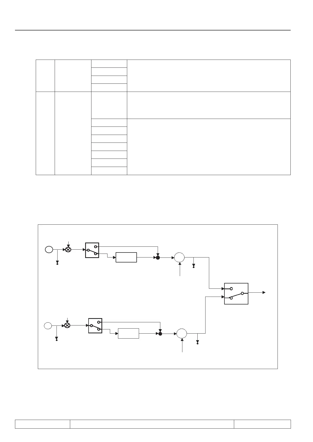
7.11.10.1 Position values
The position values of encoder 1 and 2 are determined as follows.
Z/N
ec.33
ec.60
ec.29
ec.4/ec.5 or ec.56/57
Z/N
ec.34
ec.61
ec.30
ec.14/ec.15 or ec.58/59
ru.54
ch 1
ch 2
-
-
ec.6
ec.16
see chapter
Encoder gear factor
see chapter
Encoder gear factor
see chapter
Posi / Syn
7.11.10.2 System offset
The system offset is used to:
• set the actual position to the reference point
• Compensate overows at multiturn encoders after power-on
 Loading...


