Motor data and controller adjustments of the asynchronous motor
© KEB, 2012-10 COMBIVERT F5-A, -E, -H Page 7.5 - 5
7
uF.10: max. voltage mode
Va-
lue
Modulation Description
0
100 % v/f / 100% vol-
tage
without overmodulation; all limitations 100% of modulation factor
1
110 % v/f / 110% vol-
tage
with overmodulation; all limitations 110% of modulation factor
2
200 % V/f / 100% vol-
tage
limitation of the voltage generating functions 200 %; limitation before modu-
lator 100% of modulation factor
3
200 % V/f / 110% vol-
tage
limitation of the voltage generating functions 200 %; 110 % output voltage
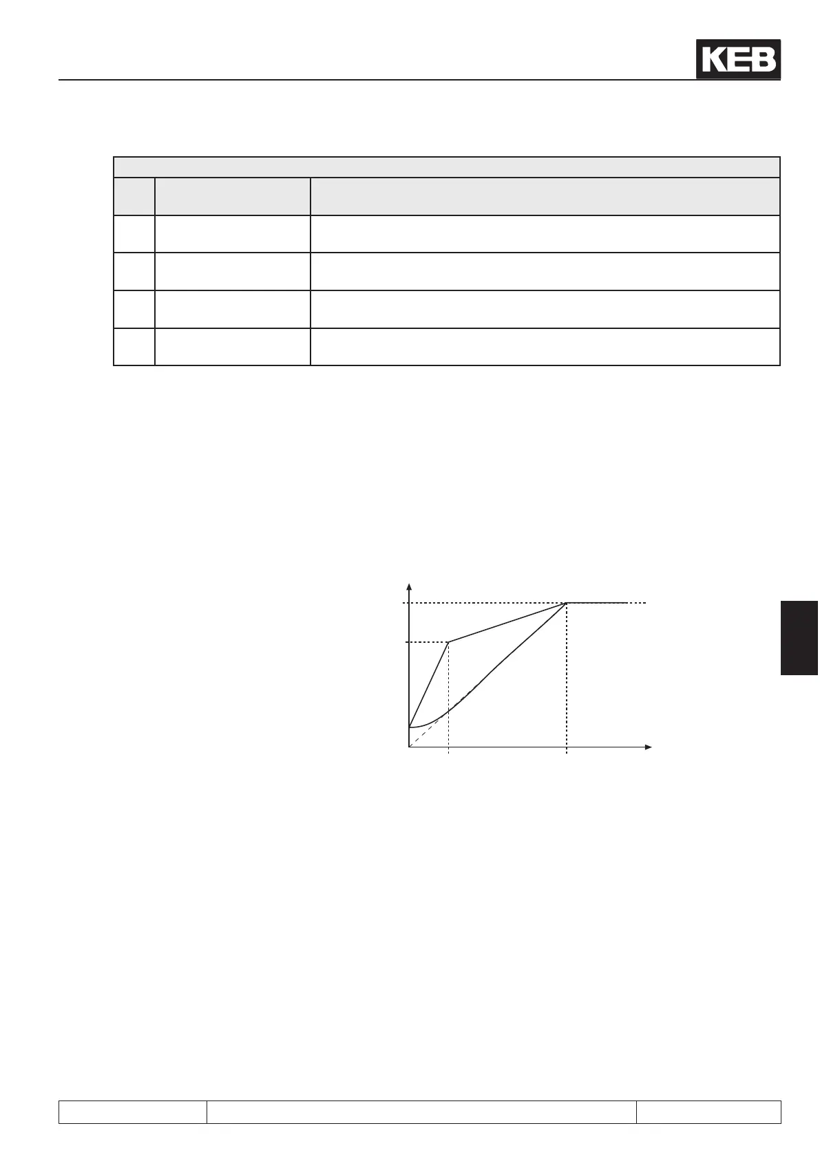
7.5.1.3 Additional rated point (uF.02 / uF.03)
To adapt the V/f-characteristic to special conditions an additional rated point can be specied with uF.02 and
uF.03. uF.02 denes the frequency and uF.03 the voltage. At uF.02 = 0 Hz the adjustment is ignored. The
parabolic characteristic is activated with uF.02 = „-1: parabolic characteristic". Then parameter uF.03 has no
function.
Figure 7.5.1.3 Additional point of sup-
port
ru.42: modulation grade
U
A
f
out
uF.01
100%
uF.00
uF.03
uF.02
uF.02 = -1: Parabolic characteristic
0,0...400 Hz; Default = 0,0 Hz
uF.03 = 0,0...100,0 %; Default = 0,0 %
7.5.1.4 Voltage stabilisation (uF.09)
The DC link voltage and thereby the directly dependent output voltage can be changed by uctuations of the
mains voltage or the load. In the case of enabled voltage stabilization the uctuations of the output voltage are
compensated. I.e., 100% output voltage correspond to the value set in uF.09 , but maximally 110% · (UZK / √
2), depending on the setting of uf.10. This function further allows operation of motors with a low nominal voltage
at the inverter.
 Loading...


