Page 7.6 - 8 COMBIVERT F5-A, -E, -H © KEB, 2012-10
Motor data and controller adjustments of the synchronous motor
7.6.2 Speed-controlled operation with encoder feedback
7.6.2.1 Controller structure
Diagram of the controller structure for operation with encoder feedback, see chapter 7.6.4.
7.6.2.2 Absolute position (encoder 1)
The system position acquires the mechanical misalignment between rotor and zero position of the mounted
encoder system. This system position is preset at standard KEB motors in factory setting.
In order to operate a customer motor with encoder system it is necessary to make the automatically calibration
to detect the system position.
The following steps must be done:
- open control release ST (terminal X2A.16)
- Initial settings described in chapter 7.6.1 must be done.
- Enter increments per revolution in Ec.01/ Ec.11
- Check dircetion of rotation. The speed display ru.09/ ru.10 must be positive in case of manual forward
rotation. Otherwise the direction of rotation can to be changed as dened in chapter 7.11.7.
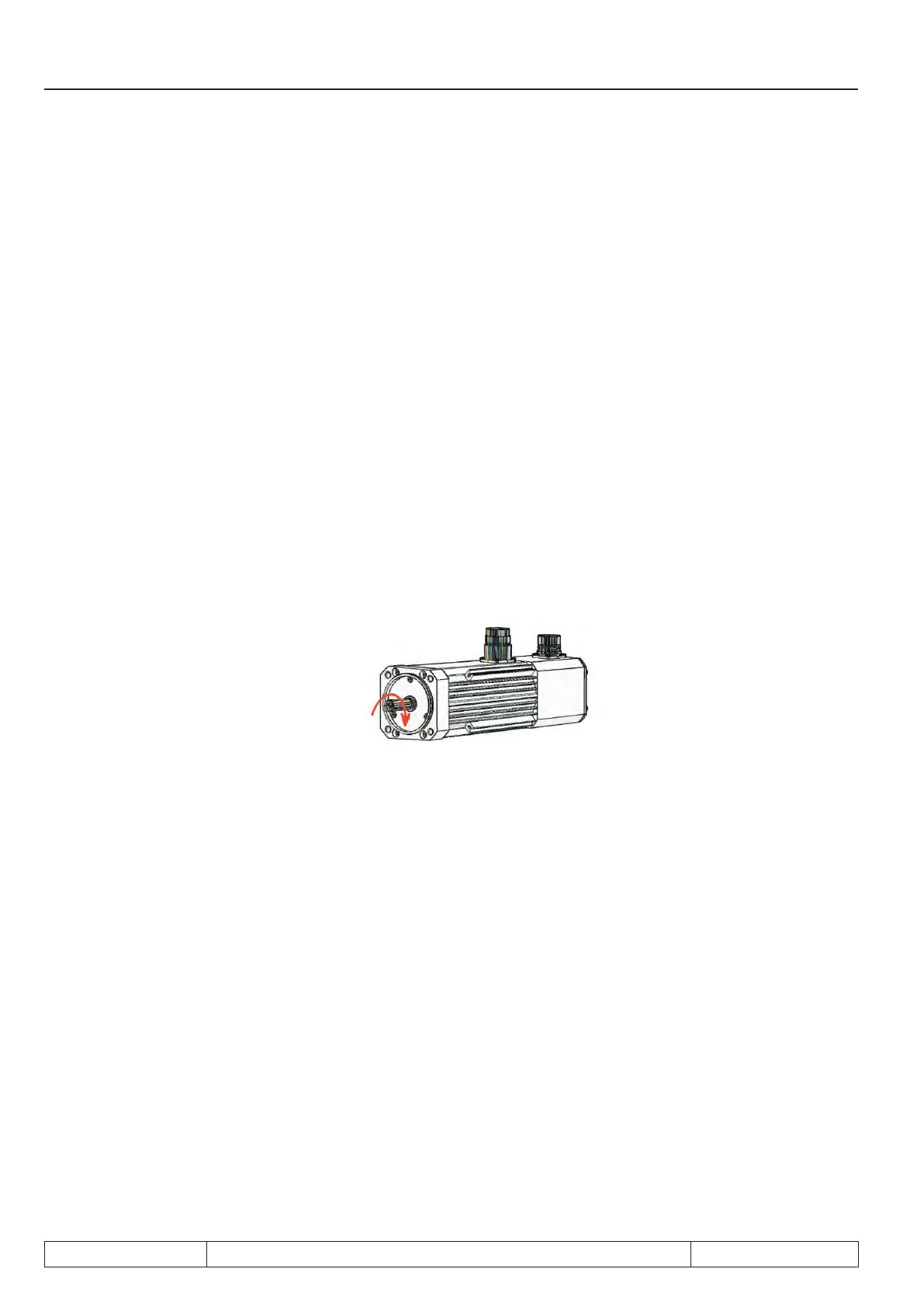
- Attention has to be paid to in-phase connection (connect inverter terminals U, V, W on the motor terminal
board with the appropriate contacts). If the cabling is correct, the setting "clockwise rotation" will lead to
the following sense of rotation:
- Motor must mandatory run with no load.
- Enter „2206“ in Ec.02/ Ec.12 and conrm message (depending on encoder interface).
- Close control release
- The motor is excited with motor current dr.23. Subsequently a forward-/reverse running identication is
executed. On successful conclusion the inverter state displays ru.00 = 127 (drive data calculated).
- the Error E.ENC1 respectivelyor E.EnC2 is triggered if the motor cannot rotate free or if the direction of
rotation is not conrm with the phase position.
- Open control release after successful trimming (ru.00 = 127 drive data calculated).
The current system position is written into the respective parameter (Ec.02/ Ec.12).
Compatibility with S4-systems
If a S4 system shall be replaced by a F5-S, the system position for the F5 inverter can be calculated from the
data of S4:
Ec.02 or Ec.12 = system position F5-S
Ec.07 = system position S4
Pole-pair number = rated frequency * 60 / rated speed
 Loading...


