Control Units
© KEB, 2012-10 COMBIVERT F5-A, -E, -H Page 3.1-3
3
3. Hardware
3.1 Control circuit F5-A, -E, -H
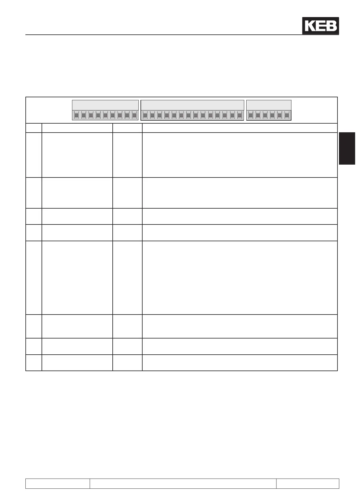
3.1.1 Terminal strip X2A
123456789
10 11 12 13 14 15 16 17 18 19 20 21
22 23 24 25 26 27 28 29
PIN Function Name Explanation
1
2
3
4
+ Set Value input 1
- Set Value input 1
+ Set Value input 2
- Set Value input 2
AN1+
AN1-
AN2+
AN2-
The input signal 0...±10 V; 0...±20 mA and 4...20 mA is determined with
An.00/
An.10 dened. Specication and control see chap. 7.2.2.
Resolution: 12 Bit (11 Bit at F5 servo in the A-housing, Ri = 30 kΩ, scan
time: 1 ms / at fast setpoint setting: 250 µs
(see chapter 7.4.2)
5
6
Analog Output 1
Analog Output 2
ANOUT1
ANOUT2
The variable for outputting at analog output is determined with An.31/
36. Specication and control see chap. 7.2.11.
Voltage range: 0...±10V, Ri = 100 Ω, Resolution: 10 Bit,
PWM-Frequency: 3.4 kHz, lter response 1. order: 178 Hz
7 +10 V output CRF
Reference voltage output +10 VDC +5% / max. 4 mA for set value poten-
tiometer
8
9
Analog Mass
Analog Mass
COM
COM
Mass for analog in- and outputs
Mass for analog in- and outputs
10
11
12
13
14
15
16
17
Progr. input 1
Progr. input 2
Progr. input 3
Progr. input 4
Progr. input forward
Progr. input reverse
Progr. input control re-
lease
Progr. input reset
I1
I2
I3
I4
F
R
ST
RST
Specications, control and programming of the digital inputs see chapter
7.3
All digital inputs are free programmable. The control release
is rmly linked with the input ST, but can be occupied with additional
other functions.
Ri = 2.1 kΩ
Scan time: 1 ms
18
19
Transistor Output 1
Transistor Output 2
O1
O2
Specications, control and programming
see chapter 7.3.12...7.3.22,
a total of max. 50 mADC for both outputs
20
21
+24 Voutput
20...30 V-Input
U
out
U
in
approx. 24V DC output (max.100 mA)
Voltage input for ext. supply, potential 0 V X2A.22/23
22
23
Digital Mass
Digital Mass
0 V
0 V
Potential for digital in-/outputs
Potential for digital in-/outputs
 Loading...


