Page 7.3 - 40 COMBIVERT F5-A, -E, -H © KEB, 2012-10
Digital in- and outputs
7.3.21Invertingofags(do.25...do.32)
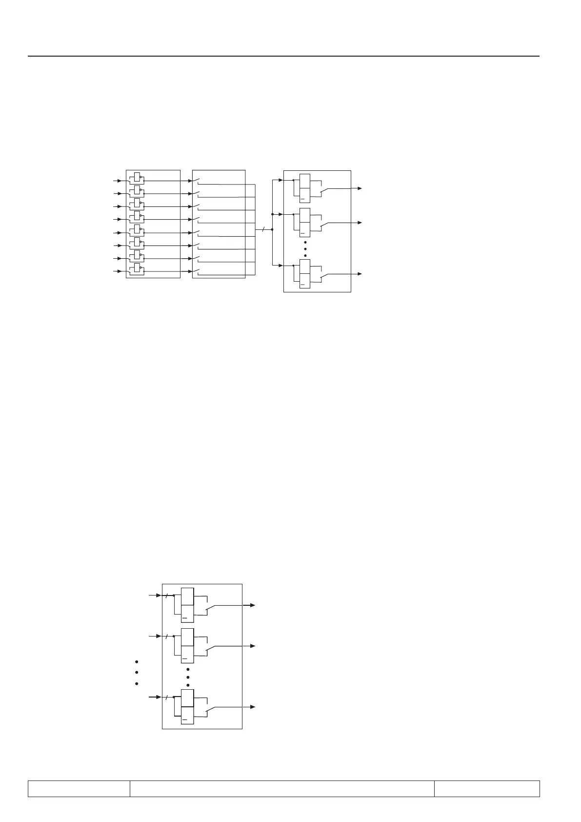
Fig. 7.3.21 Inverting and selection of ags
8
1
1
1
1
do.25...do.32
Bit 0
Bit 1
Bit 2
Bit 3
Bit 4
Bit 5
Bit 6
Bit 7
1
2
4
8
16
32
64
128
do.33...do.40
1
2
4
8
16
32
64
128
1
1
1
1
&
>
1
0
1
Bit 0
&
>
1
0
1
Bit 1
&
>
1
0
1
Bit 7
do.41
O1
O2
OD
With parameters do.25...do.32 each of the 8 ags (bit 0...7) from logic step 1 can be inverted separately.
With this function it is possible to set any chosen ag as non-ag. The parameter is bit-coded. According to
Fig. 7.3.18 the weighting of the ag to be inverted must be entered in do.25...do.32. If several ags shall be
inverted, the sum is to be formed.
7.3.22Selectionofags(do.33...do.40)
In the second logic step a selection of the ags of the rst logic step can be made. The selection is done for
each output separately, where one can choose between none and up to all 8 ags.The value of the selected
switching conditions must be entered in do.33...do.40 in accordance with g. 7.3.18. The sum is to be formed
if several ags shall be selected.
7.3.23 AND connection for outputs (do.41)
After the ags are selected for each output, now it can be determined how these are linked. As a default all
ags are OR operated, i.e. if one of the selected ags is set, the output switches.Another possibility is the AND
operation which can be adjusted with do.41. AND operation means, all selected ags must be set before the
output switches.
Fig. 7.3.23a. Linking the outputs
&
>
1
0
1
Bit 0
8
&
>
1
0
1
Bit 1
8
do.34
&
>
1
0
1
Bit 7
8
do.40
do.41
do.33
O1
O2
OD
 Loading...


