Page 7.12 - 10 COMBIVERT F5-A, -E, -H © KEB, 2012-10
Posi- and synchronous operating
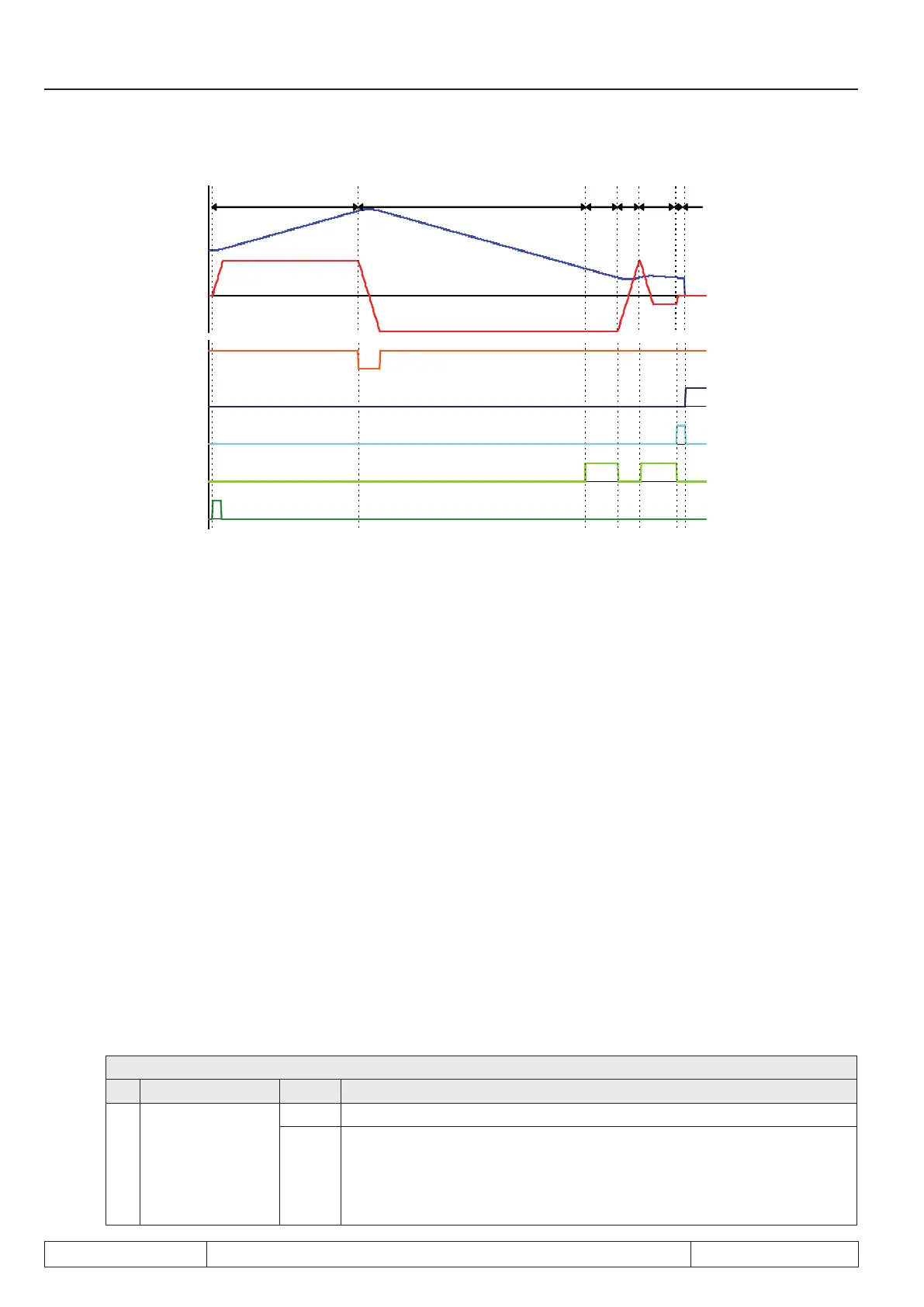
1 2 3 4 5 6 7
Start approach
to reference
point
Reference
point switch
Target window
reached
Approach to
reference point
completed
ru.54: actual
position
ru.02: Set
speed
Limit switch
right
1. PS.21 positive
Drive accelerates with ramp from PS.20 and seeks in forward direction for the reference switch
2. Run-on to the limit switch
Reverse and seek in the other direction of rotation
3. Overdriving of the reference switch
(because stopping the drive left to the reference switch is selected in PS.14, the switch must be ap-
proached from the right)
4. Reversing and running onto the reference switch in direction of rotation clockwise
5. Reversing on the reference switch and driving free with drive free speed (PS.21/ PS.22)
6. Stopping of the drive with the ramp from PS.20
Setting of the signal "target window reached"
Wait for the damping period of 100ms
7. Overwriting the current actual position (ru.54) with the reference point position(PS.17)
Resetting of the signal "target window reached"
Setting of the signal "approach to reference point completed"
Stopping of the drive left of the reference point (programmable via PS.14)
7.12.2.6 Reference point / manual setting
7.12.2.6.1 Over PS.14
If no reference point switch is provided in the application, the drive can also be manually referenced:
PS.14: Mode of position reference
Bit Meaning Value Explanation
6 Manual setting
0: off No manual setting
64: on
The drive is approached in inching mode to reference point and then
"manual setting = on" (bit 6) is set. The reference point position (PS.17)
is taken as actual position (ru.54). The switching condition "approach to
reference point completed” (do.00...07, value 29) is set, the software limit
switch function can be used.
 Loading...


