Control Units
© KEB, 2012-10 COMBIVERT F5-A, -E, -H Page 3.1-7
3
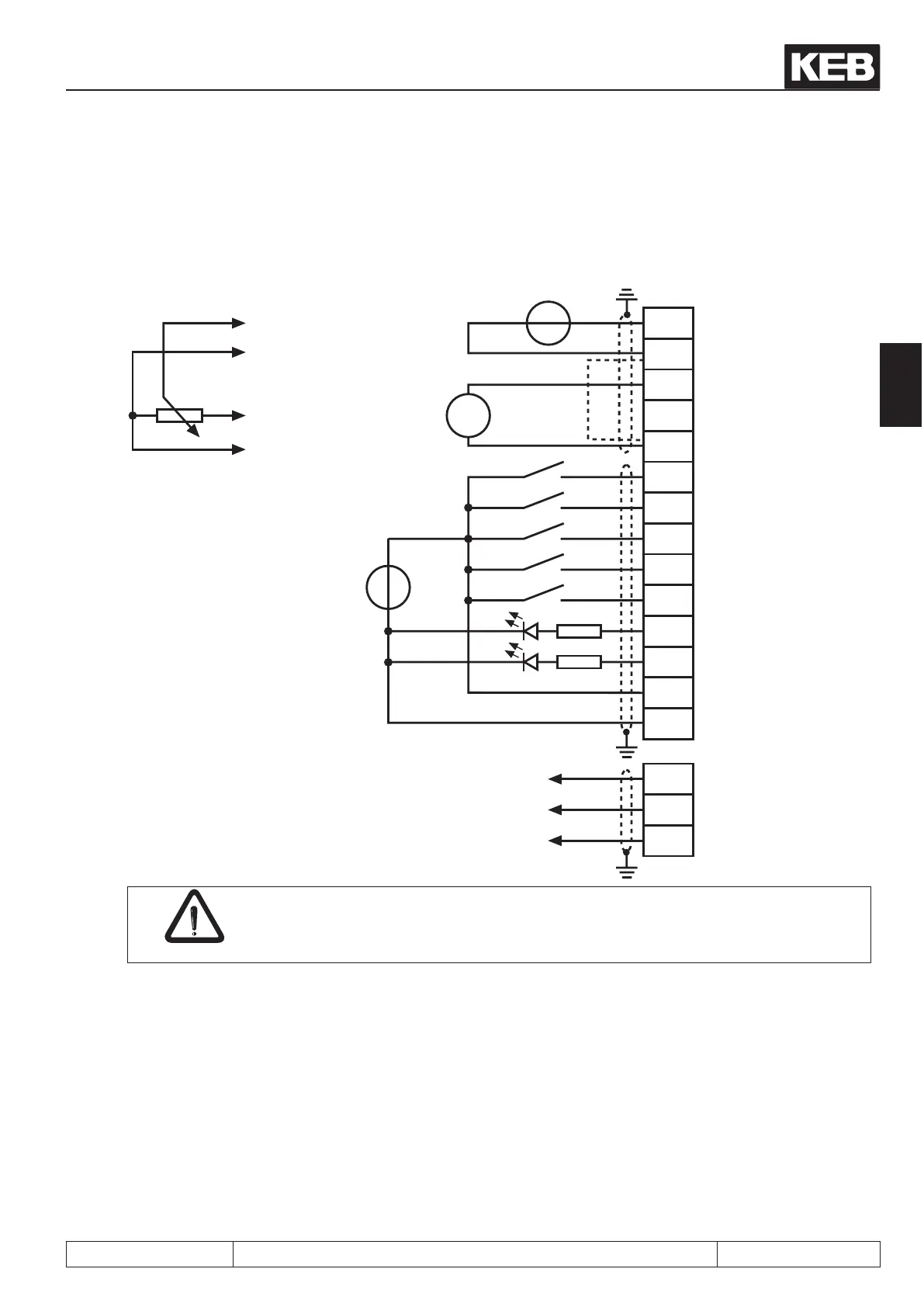
3.2.2 Connection of the control terminal block
1)
Connect potential equalizing line only if a potential difference of > 30 V exists between the
controls. The internal resistance is reduced to 30 kΩ.
In case of inductive load on the relay outputs a protective wiring must be provided (e.g. free-wheeling diode) !
The control card must always be supplied with an external power source. Thus the control remains
in operation even when the power unit is switched off. To prevent undened conditions at external power
supply the basic procedure is to rst switch on the power supply and after that the inverter.
The connections of the control terminal blocks and encoder inputs have safe isolation according to EN 50178.
Setpoint potentiometer
3…10 kΩ
external voltage supply
20…30 V DC ±0 %
1 A
Setpoint signal
0…±10 V DC
Analog output
±10 V DC
max. 5 mA
max. 30 V DC
0.01…1 A
 Loading...


