Page 7.1 - 20 COMBIVERT F5-A, -E, -H © KEB, 2012-10
Operating and appliance data
7.1.7 Description of the SY (System) - Parameters
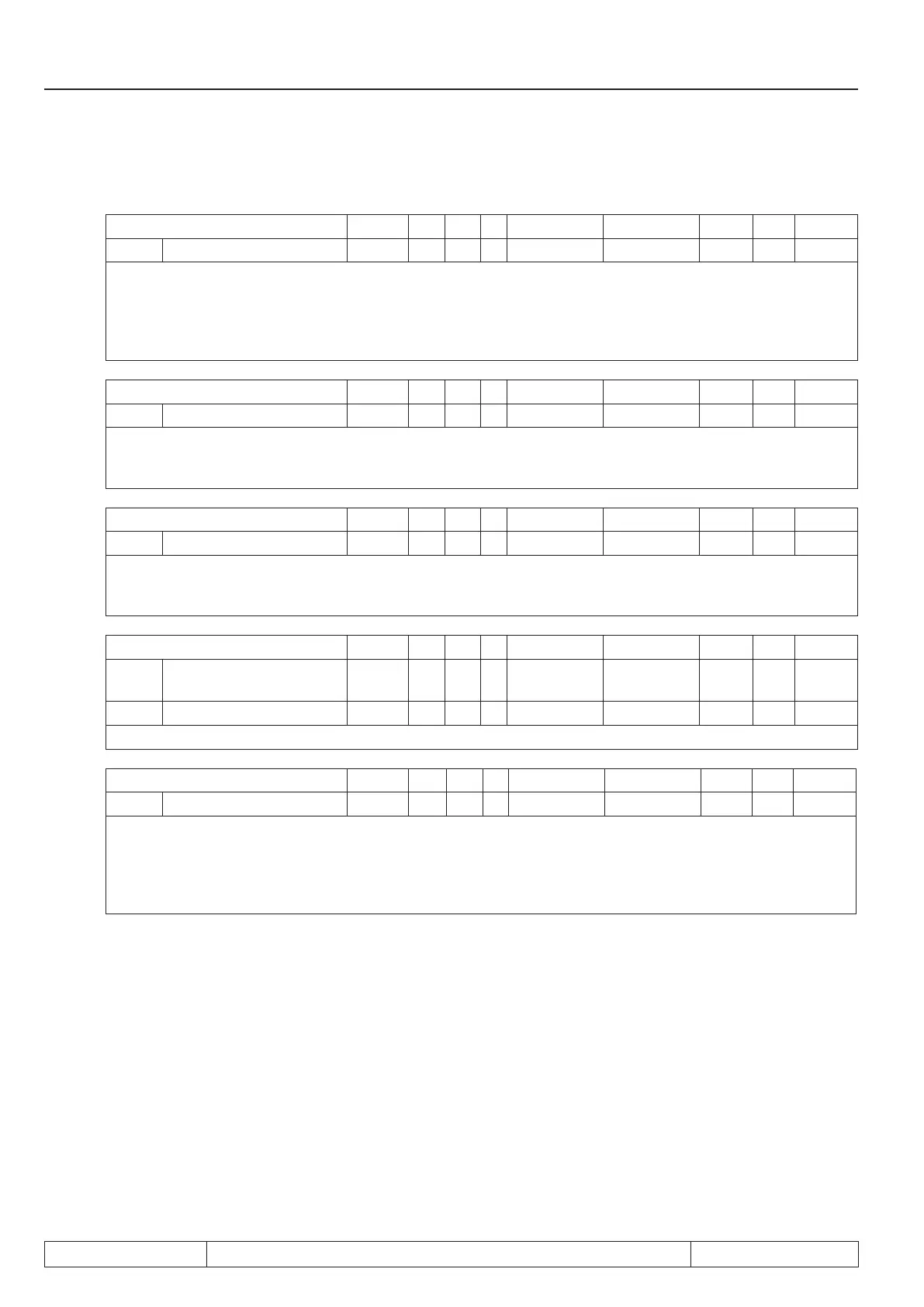
Parameter Addr. R PG E Min. value Max. value Res. [?] Default
SY.01 Watchdog cycle 0001h RO - - 0000 255 1 hex -
The monitoring of communication in the synchronous bus operation occurs with parameter SY.01, which is
evaluated in a eld bus operator (e.g. DIASBus). Triggering of the malfunction occurs via Pn.05, Pn.06, SY.57,
like monitoring of the external interface at standard operators. The function is switched off at a power on reset
(SY.01 = 0). A value > 0 switches on the monitoring. The number of cycles is adjusted that shall occure until
a malfunction is triggered.
Parameter Addr. R PG E Min. value Max. value Res. [?] Default
Sy.02 Inverter identier 0002h RO - - 0000 9999 1 hex -
An unique number is assigned to each type of frequency inverter which identies the inverter. This value is
used for example by COMBIVIS to load the correct conguration les.Sy.02 can be written with the indicated
value (e.g. for identication of download lists).
Parameter Addr. R PG E Min. value Max. value Res. [?] Default
Sy.03 Power unit code 0003h RO - - -255 255 1 - -
On the basis of the power circuit identication the control recognizes the used power circuit respectively a
change of the power circuit and adjusts certain parameters accordingly. To accept a new P-Id enter positive
values (see chap. 8 „E.Puch“).
Parameter Addr. R PG E Min. value Max. value Res. [?] Default
Sy.04 Conguration data se-
lection
0004h RO - - 0 24 1 - -
SY.05 Conguration data 0005h RO - - -32727 32767 1 - -
This parameters give information about the appropriate cong-data of the inverter.
Parameter Addr. R PG E Min. value Max. value Res. [?] Default
Sy.06 Power unit code 0006h RW - + 0 239 1 - 1
The address if the inverter shall be responded via "COMBIVIS" or another control can be adjusted in SY.06.
Values between 0 and 239 are possible, the default value is 1. If several inverters are operated on the bus
simultaneously, it is absolutely necessary to assign different addresses to them, since otherwise it leads to
communication failures because several inverters may answer at the same time. The description of the DIN
66019II protocol (C0.F5.01I-K001) contains further information to this.
 Loading...


