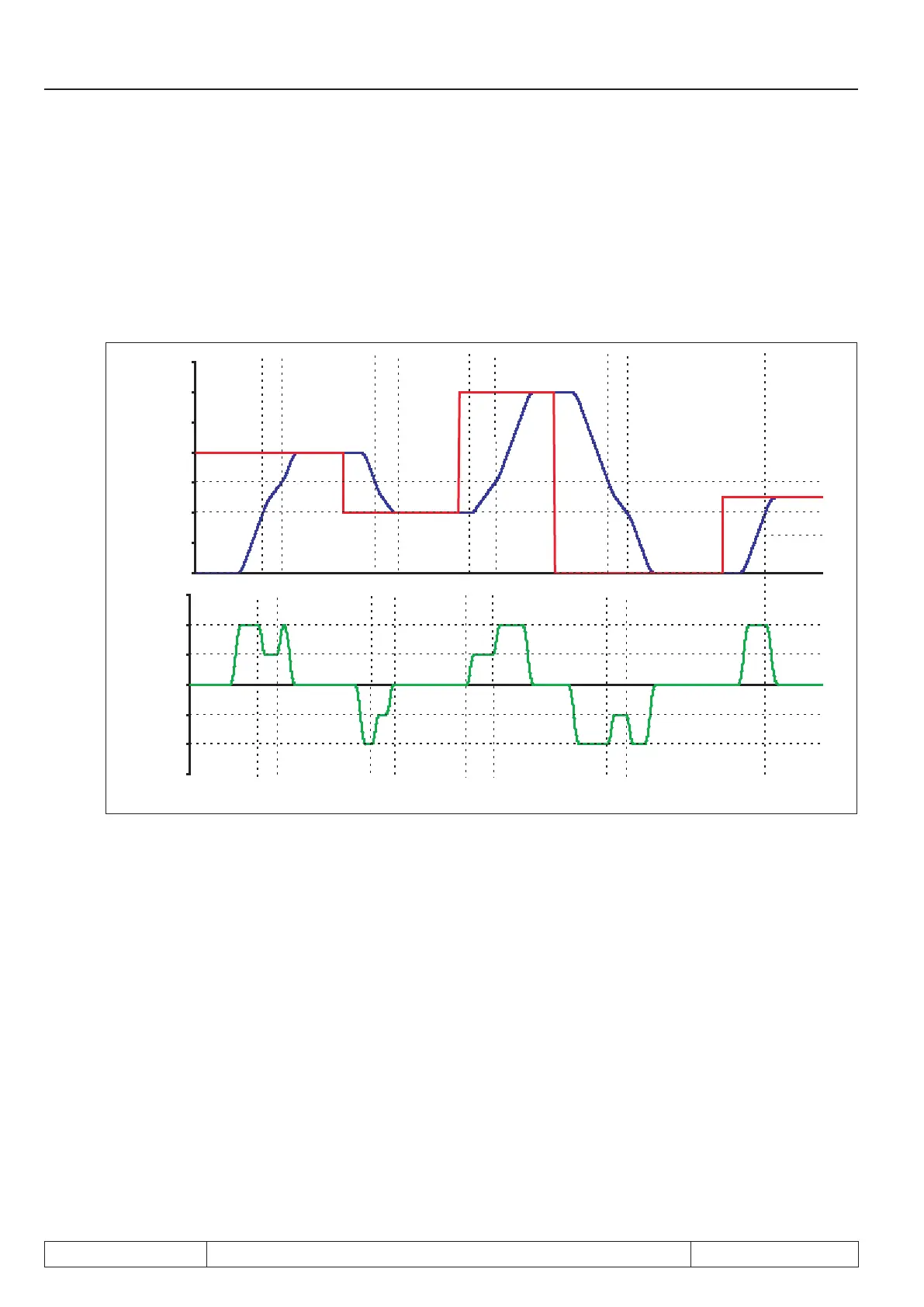
Example for a singlepositioningwithvariablemaximumprolespeed:
PS.00 bit 4 = 16
For an application, the drive shall always run with a lower prole speed between 2 positions
(e.g., joint in traversing rail). By switching the set, parameter oP.10 is decreased in this range.
After reaching this range, the drive decelerates according to the adjusted deceleration and jolt values to the
new maximum prole speed. This insures that during every positioning to an arbitrary position, the maximum
speed for this range is observed without the need for intervention by a superior control.
time
Set
speed
target
position
actual
position
7.12.4.8 Posi mode / sequential positioning
With the sequential- or index-positioning, it is possible to run to several positions consecutively and, respec-
tively, traverse these with a dened speed.
Sequential positioning is meant, if several target positions are dened in the inverter
which are to be processed in a xed sequence.
A possible example for a sequential positioning would be a drive that lowers a drill head. The drilling process
shall consist of 5 positioning steps:
● fast lowering of the drill with speed A from the starting position "0" up to position "1" ("1" = position
just before the material surface)
● slow penetration into the material (position "1" to "2") at speed B
● somewhat faster lowering (at speed C) during drilling of the material up to position "3"
● withdrawal of drill from the material at speed D, back to position "1"
● return to starting position "0" at speed A and stop there
This whole process can be realised using the sequential positioning.
To that end, so-called "blocks" are dened for every positioning step. Each block is marked by an index (i.e.,
Page 7.12 - 38 COMBIVERT F5-A, -E, -H © KEB, 2012-10
Posi- and synchronous operating
 Loading...


