Speed measurement
© KEB, 2012-10 COMBIVERT F5-A, -E, -H Page 7.11 - 5
7
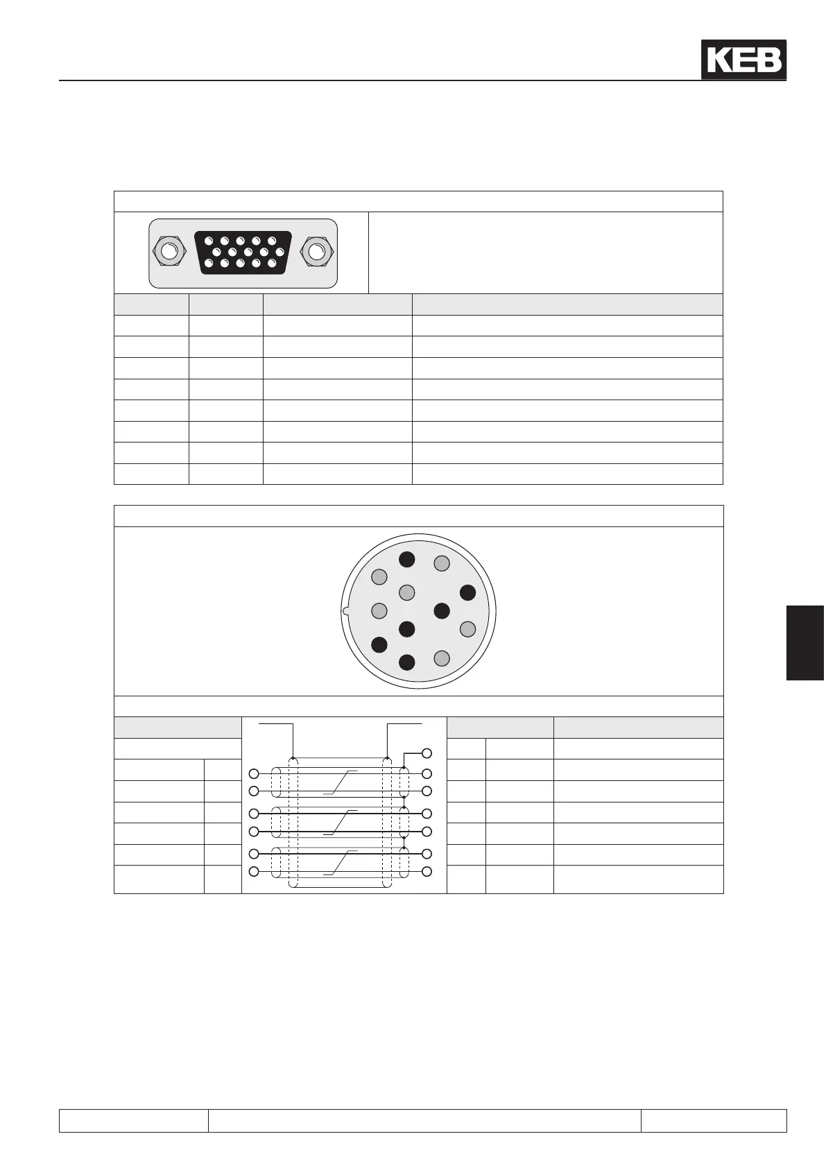
7.11.2.2 Resolver evaluation (standard at F5-S)
Fig.7.11.2.a Resolver interface channel 1 (X3A)
5432 1
10 9876
15 14 13 12 11
Only when the inverter is switched off and the vol-
tage supply is disconnected the plugs may be pulled
out or plugged in !
Signal X3A KEB servo motor Description
SIN - 3 1 Sinus signal cable inverted
SIN+ 8 10 Sinus signal cable
REF- 5 5 Reference signal inverted
REF+ 10 7 Reference signal
COS- 4 2 Cosinus signal cable inverted
COS+ 9 11 Cosinus signal cable
GND 14 - Shielding of the signal cables
Shield housing housing shielding of the hole cable
Fig. 7.11.2.b Resolver connector at the KEB servo motor
1
2
3
4
5
6
7
8
9
10
11
12
Fig. 7.11.2.c Resolver cable
housing
housing Core color
14 GND
SIN- 1 3 SIN - red
SIN+ 10 8 SIN+ blue
REF- 5 5 REF- yellow
REF+ 7 10 REF+ green
COS- 2 4 COS- pink
COS+ 11 9 COS+ gray
 Loading...


