The general rotary table mode is selected with PS.27:
PS.27: Index mode
Bit Meaning Value Explanation
1...3
Position
setting
8: Rotary table with
path optimization
The position on the round table is always approached on the
shortest path , i.e., the drive approaches the position from the
right or the left.
10: Rotary table
without path optimi-
zation
The position on the round table is always approached from one
direction. The sign of the position setpoint determines the direc-
tion of the positioning
12: Round table re-
lative (round axis)
The new target position is set relative to the current target
position.
0, 2, 4, 6, 14 Not for rotary table
The different round table modes were created for different applications.
7.12.
4.10.1 Rotary table with path optimization
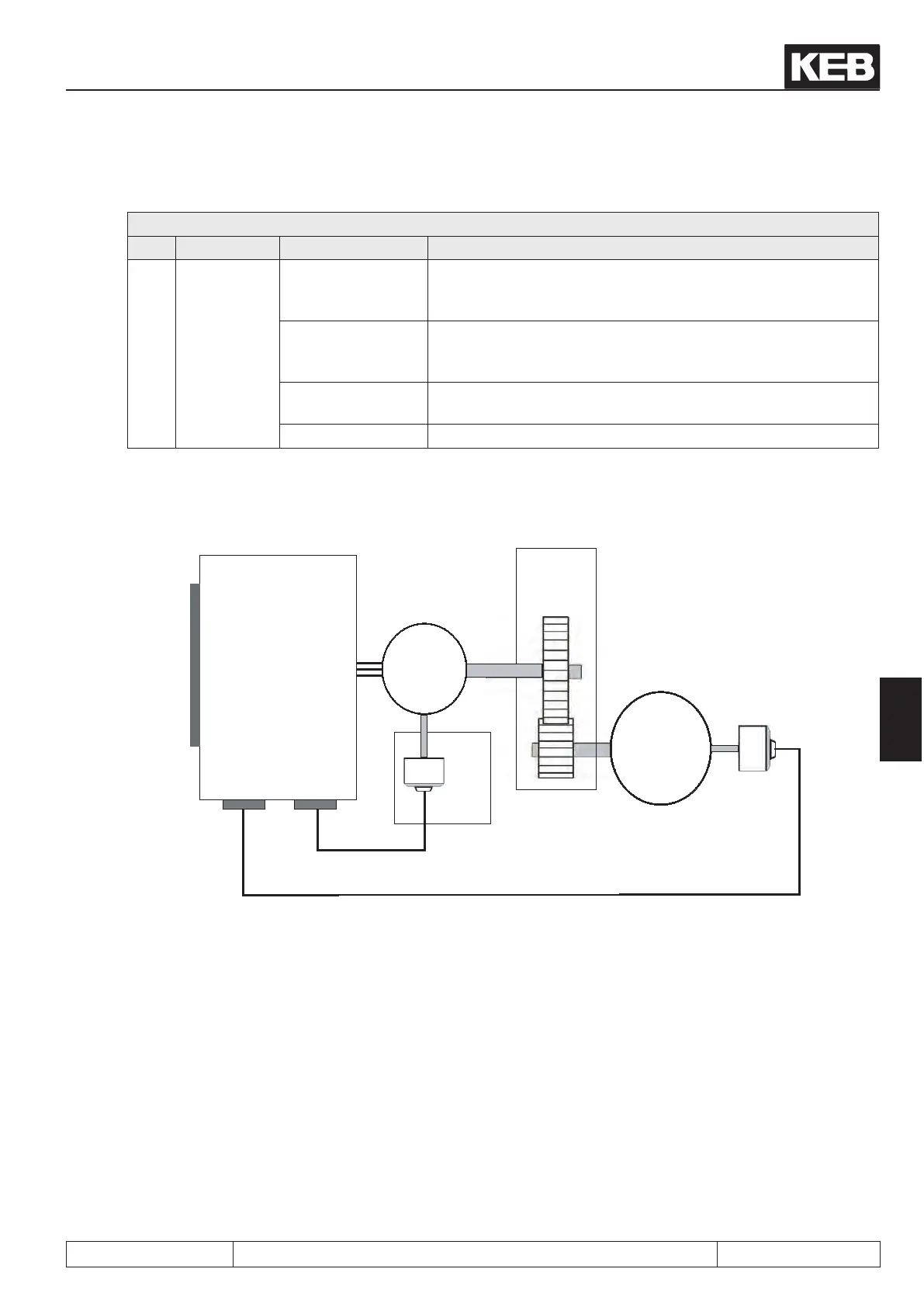
inverter
F5A-S
or
F5A-M
control terminal block X2A
X3B
Encoder
channel
2
X3A
Encoder
channel 1
M
3~
Motor position
encoder
Gear
Rotary table
Rotary table
position
encoder
This mode is particularly suitable for rotary table applications where a second encoder is used for the rotary
table position. Here, the gear backlash cannot cause a position error and the target position can be approached
precisely from both directions of rotation.
Here, the mode 8 "round table with path optimisation" is optimal since the shortest positioning times can be
achieved in this mode.
It is a prerequisite that the round table permits rotations in both directions.
The target position may lie only in the range of 0 to PS.39 - 1.
Posi- and synchronous operating
© KEB, 2012-10 COMBIVERT F5-A, -E, -H Page 7.12 - 53
7
 Loading...


