Operating and appliance data
© KEB, 2012-10 COMBIVERT F5-A, -E, -H Page 7.1 - 5
7
7.1.4 Explanation to parameter description
Legend:
Addr. = Address
PG = programmable → + = programmable
- = not programmable
E = ENTER → + = yes
- = no
R = Right → RO = Read only
RW = Read and write
KB = Keyboard
1)
= Resolution and value range depending on ud.02
Min.
value
= Minimum value
Max.
value
= Maximum value
Res. = Resolution
Default = Default value
[?] = Unit
7.1.5 Description of the ru-Parameters
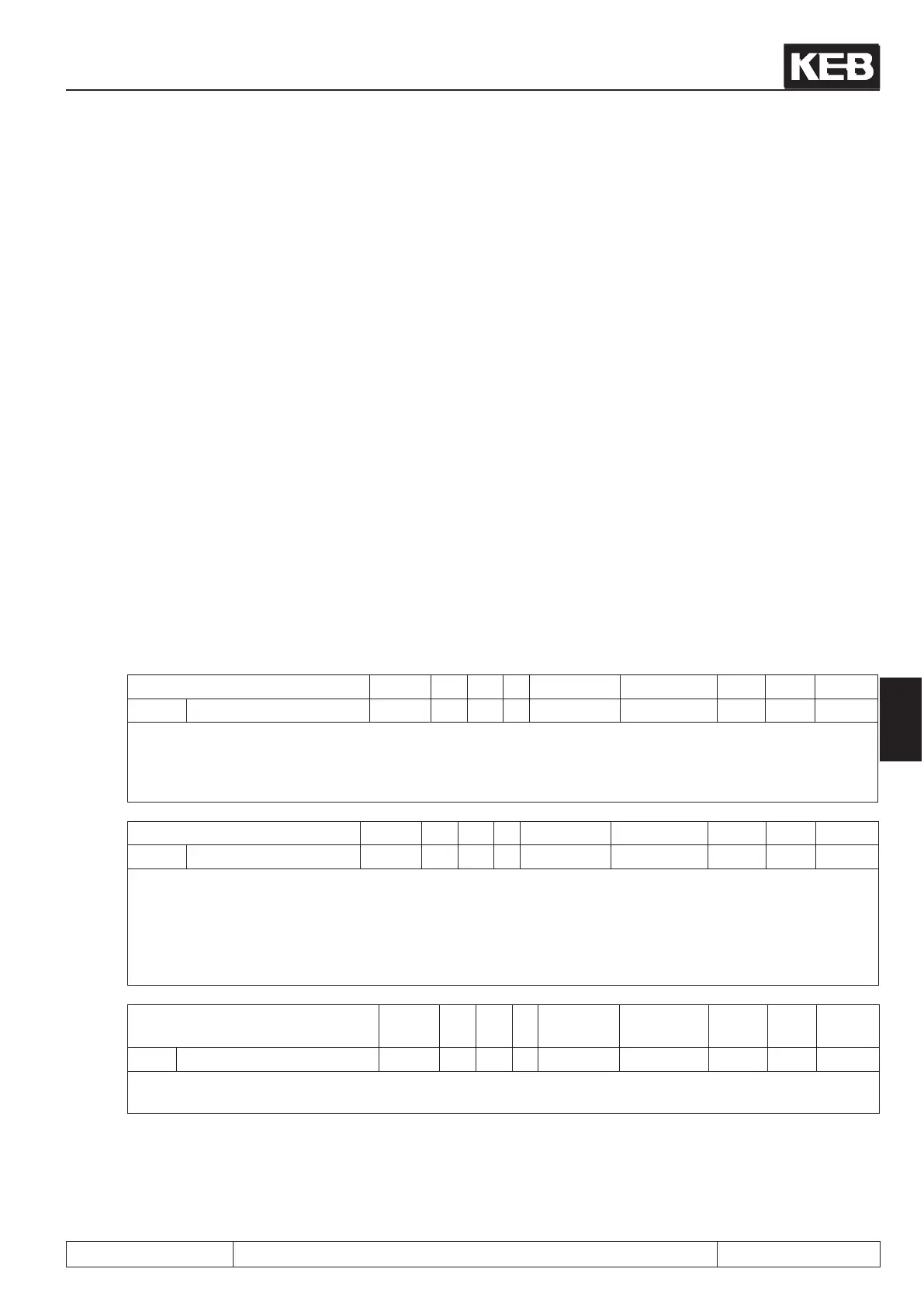
Parameter Addr. R PG E Min. value Max. value Res. [?] Default
ru.00 inverter state 0200h RO - - 0 255 1 - 0
The inverter status shows the current operating condition of the regenerative unit. In the case of an error
the current error message is displayed, even if the display has already been reset with ENTER (error-LED
on the operator is still blinking). For more information about status messages as well as its cause and re-
moval refer to Chapter 8 „Error Diagnosis“.
Parameter Addr. R PG E Min. value Max. value Res. [?] Default
ru.01 set value display
1)
0201h RO - - -4000 4000 0.125 rpm -
Display of the actual set speed. For control reasons the set speed is displayed even if control release or
direction of rotation are not switched. If no direction of rotation is set, the set speed for clockwise rotation
(forward) is displayed.
A counter-clockwise rotating eld (reverse) is represented by a negative sign. Precondition is the phase-correct
connection of the motor.
Parameter Addr. R PG E Min.
value
Max. value Res. [?] Default
ru.02 ramp output display 0202h RO - - -4000 4000 0.125 rpm -
The displayed speed corresponds to the synchronous speed output at the ramp output. The output is displa-
yed like ru.01.
 Loading...


