Motor data and controller adjustments of the synchronous motor
© KEB, 2012-10 COMBIVERT F5-A, -E, -H Page 7.6 - 15
7
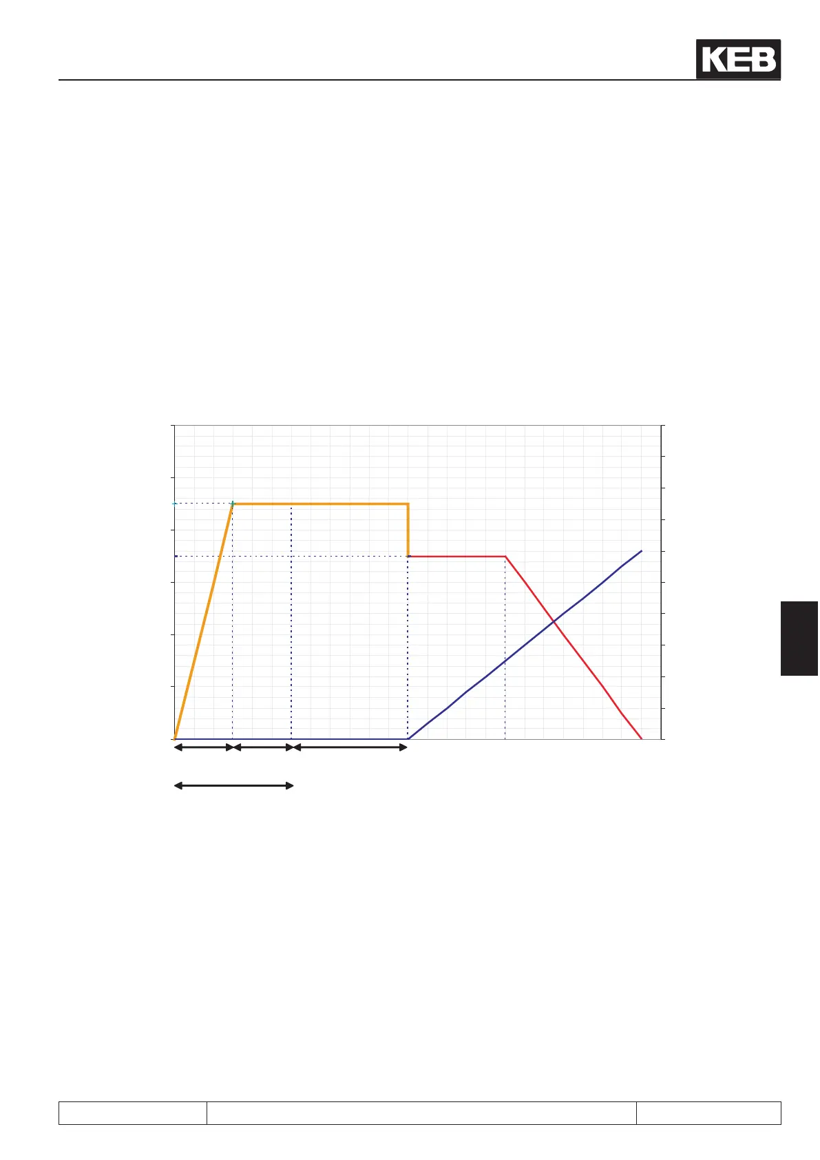
7.6.3.4 Standstill and starting phase
It must be secured that the rotor is in a dened position after switching on of the control release ST. Therefore
a DC current is injected at standstill. Then the rotor rotates into its origin position.
The standstill current is ½ of the rated current and can be adapted in parameter nn.10 in default setting after
operation of Fr.10.
The times (Pn.35 and Pn.36) of the brake handling are active for standstill operation. In order that the rotor does
not vibrate after setting the control release, the current reaches the setpoint value in a half of the time adjusted
in Pn.35 "premagenetising time". (see picture 7.6.3.4a)
The half current-dependent load torque is acceptable as mechanical load (e.g. ¼ of the rated torque at ½ of
rated current at standstill).
Picture 7.6.3.4a
Current (A) Speed (rpm)
Standstill current
Stabilisation
current
Ramp output
ru.02
Current [A]
Speed [rpm]
nn.03nn.02
Pn.36
Pn.35
½Pn.35 ½Pn.35
200
0
160
1240
80
40
180
140
100
60
20
12
0
10
8
6
4
2
nn.10
nn.01
Speed search
The rotor rotates at some applications when the modulation is switched on. The current speed can be deter-
mined with Pn.26 "speed search condition". (For further information seechapter 7.13.4 SSF)
Additional start ramp
In order to leave the critical range of small speed at starting and stopping there is an additional ramp for this
range.
The ramp is dened by parameter nn.08 nn.08 "startup speed" which indicates the speed range and parameter
nn.09 „startup time" which indicates the appropriate acceleration-/ deceleration time.
 Loading...


