Motor data and controller adjustments of the asynchronous motor
© KEB, 2012-10 COMBIVERT F5-A, -E, -H Page 7.5 - 9
7
Adhere to the following procedure:
- Enter motor data of the type plate into the parameter set which is to program
- possibly call and activate parameter set
- Execute the measurement dependent on the operational case in cold status respectively let the motor
warm up to operating temperature.
- Preset no direction of rotation (inverter must be in status "LS")
- Activate control release
- maximum value "250000" of parameter dr.06 starts the resistance measurement
During the determination the status display (ru.00) indicates "Cdd". Upon successful determination the motor
stator resistance is entered in dr.06. If an error occurs during determination then error signal "E.Cdd" is output.
7.5.1.7.3 Load motor dependent para. (Fr.10), controller activation
After input of the rating plate data of a new motor or after automatic measurement of the stator resistance, an
automatic optimisation of the torque and slip compensation can be carried out with Fr.10 (see chapter 7.5.1.7).
The optimisation is started by writing value "3" on Fr.10. Thereby the inverter must be in status „noP“ (no control
release). Provided that only one motor is used, the measurement can occur with direct set programming for all
parameters at once.
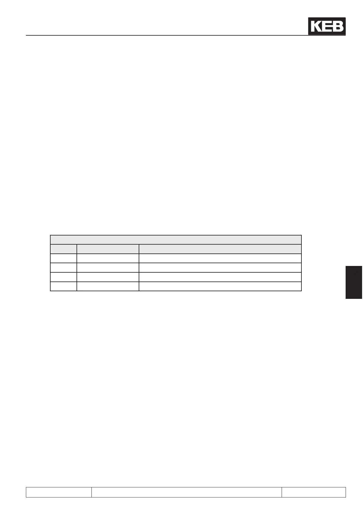
Fr.10: Load motor dependent parameter
Value Function Description
0 nished loading completed
1 uF.09 only for closed loop operation
2 act. DC link voltage only for closed loop operation
3 SMM Adjustment for torque and slip compensation
Following parameters are changed by the activation of Fr.10:
- uF.00 rated frequency = Motor rated frequency (dr.05)
- uF.01 boost = calculated value
- uF.02 additional point of support (frequency) = -0,0125 Hz (parabolic characteristic)
- uF.02 additional point of support (voltages) = 0,0%
- uF.09 voltage stabilisation = rated motor voltage (dr.02)
- uF.16 torque compensation / conguration = 1 (sign-sensitive)
- uF.17 torque compensation / amplication = 1,2 (Default value)
- cS.00 controller conguration = 34 (speed control SMM + breakdown slip limit (dr.09))
- cS.01 actual source = 2 (calculated)
- cS.04 speed control limit = 4 • nominal slip of the motor
- cS.06 KP speed controller = 50
- cS.09 KI speed controller = 500
The adaption covers approx. 90 % of the applications. For an application-specic adjustment a manual ne
adjustment can now still be carried out for an individual case.
 Loading...


