Digital in- and outputs
© KEB, 2012-10 COMBIVERT F5-A, -E, -H Page 7.3 - 23
7
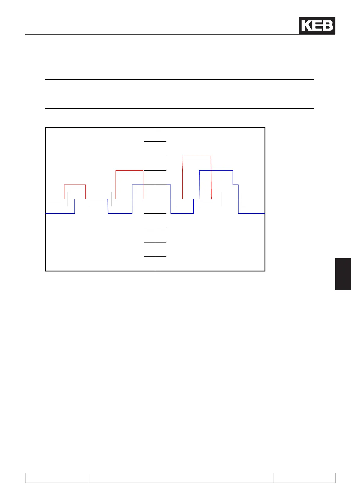
COMBIVIS 5 Scope - Knoten 0
COMBIVIS 5 Version 5.6 Registriert für: Karl E. Brinkmann GmbH D-32683 Barntrup
Druckdatum: 29.07.2009 10:26:22
640: F5A-G/V4.30 400Hz
X (ms/Teilung): 2000
CH Parameter Satz Y-Faktor (n/Teilung) Y-Null bei
A ru21 input terminal state 0 16: I1 0: no input
B ru22 internal input state 0 16: I1 16: I1
C Aus
D Aus
A
B
7.3.8 Input trigger (di.05)
As a standard the inverter is controlled with static signals, i.e. an input is set for as long as a signal is applied.
However, practice has shown that a signal may be available for a limited time only, but the input shall still
remain set. In that case the input or several inputs can be adjusted to edge-triggered ip-op. Then a rising
edge with a pulse duration that is longer than the response time of the digital lter is sufcient for switch-on.
Switch-off is effected with the next rising edge.
Control release (ST) can be set to edge-triggered ip-op, but this remains without affect on the function, since
it is a pure static signal.
 Loading...


