Analog in- and outputs
© KEB, 2012-10 COMBIVERT F5-A, -E, -H Page 7.2 - 13
7
Fig. 7.2.10 Analog output
AGND
(X2A.8 / X2A.9)
+-
ANOUT1 (X2A.5) /
ANOUT2 (X2A.6)
U
out
= 0...±11,5 V
R
B
I
max
= 5mA
R
i
< 100Ω
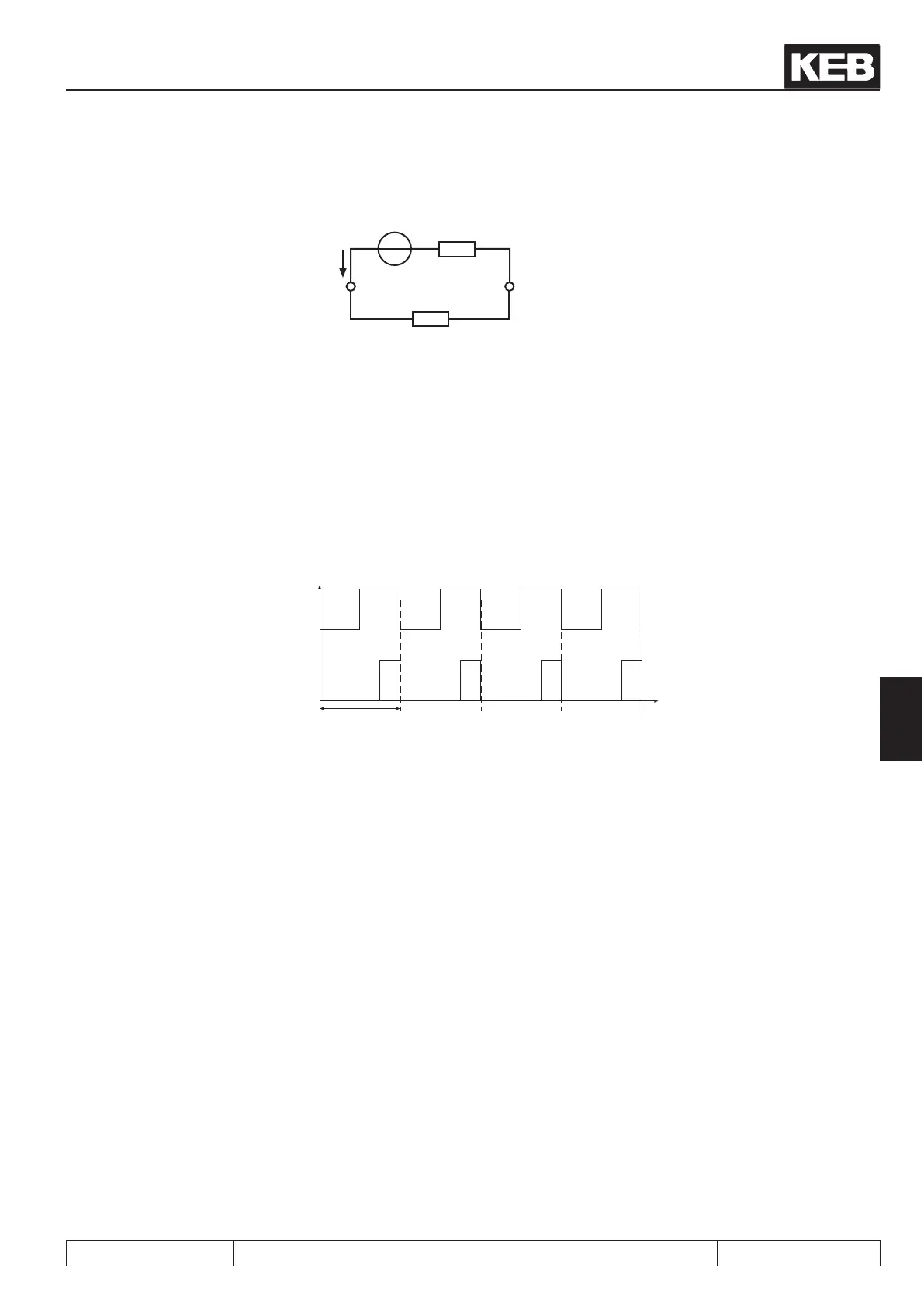
ANOUT 3 / 4, PWM outputs
Process variables, that change only slowly, as for example the power module temperature, can be output over
two virtual analog outputs (ANOUT3 and 4). This is realised through generation of a PWM-signal (pulse-width-
modulation) on a digital output. The period T can be adjusted with parameter An.46 or An.52 „ANOUT period“
of 1...240 s.
Fig. 7.2.10.a PWM - output signal
ANOUT 3/4
Input value 50 %
Input value 25 %
7.2.11 Analog Output / Display (ru.33...34 / ru.35...36)
Following parameters are used for the display of the analog outputs, before and after the characteristic ampli-
cation:
ru.33 ANOUT1 / pre ampl. display 0...±400 %
ru.34 ANOUT1 / post ampl. display 0...±115 %
ru.35 ANOUT2 / pre ampl. display 0...±400 %
ru.36 ANOUT2 / post ampl. display 0...±115 %
At the outputs ANOUT3 and 4 there is no display provided.
 Loading...


