Page 7.2 - 12 COMBIVERT F5-A, -E, -H © KEB, 2012-10
Analog in- and outputs
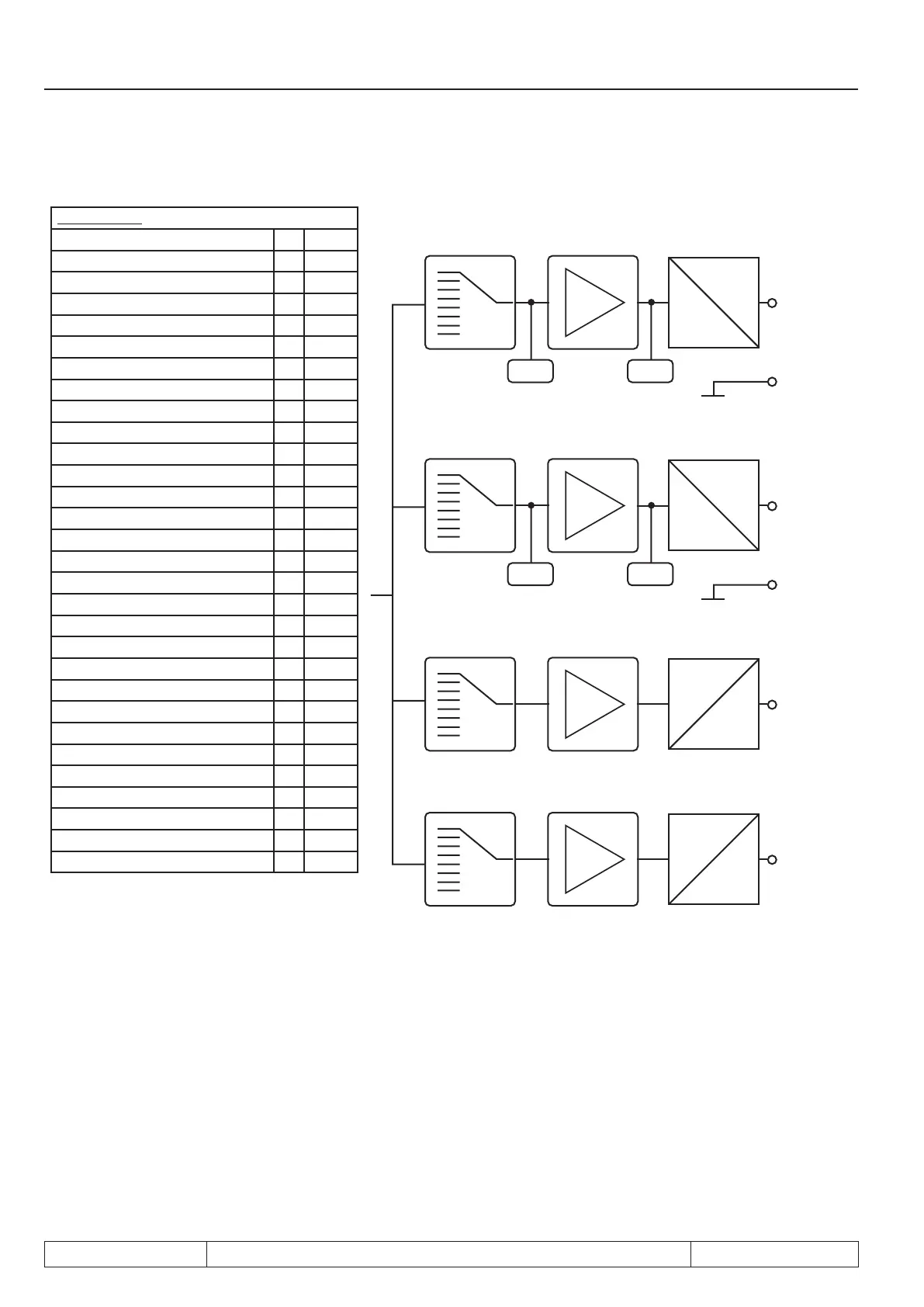
Picture 7.2.9 Principle of the analog outputs
An.31/36/41/47
Absolute actual value 0 ru.07
Absolute set value 1 ru.01
Actual value 2 ± ru.07
Set value 3 ± ru.01
Output voltage 4 ru.20
actual DC voltage 5 ru.18
apparent current 6 ru.15
active current 7 ru.17
digital setting by An.32/37/42/48 8 An.xx
External PID output 9 ± ru.52
absolute ext. PIDoutput 10 ru.52
Absolute active current 11 ru.17
Power module temperature 12 ru.38
Motor temperature 13 ru.46
Actual torque 14 ± ru.12
Absolute actual torque 15 ru.12
Set torque 16 ± ru.11
Absolute set torque 17 ru.11
System deviation/speed controller 18 -
speed reference variable 19 ± ru.02
Abs. speed reference variable 20 ru.02
Angle difference 21 ru.58
AN1 pre amplier 22 ru.27
AN1 post amplier 23 ru.28
AN2 pre amplier 24 ru.29
AN2 post amplier 25 ru.30
Active power 26 ru.81
Actual position 27 ru.54
Set position 28 ru.56
Max. torque in % 29 ru.90
An.31
An.34
An.35
X2A.5
ANOUT1
X2A.8
AGND
0...±100%
0...±10V
ru.34ru.33
An.36
An.38
An.39
An.40
X2A.6
ANOUT2
X2A.9
AGND
0...±100%
0...±10V
ru.36ru.35
An.41
An.43
An.44
An.45
PWM
100%
An.46
An.47
An.49
An.50
An.51
PWM
100%
An.52
do.0...do.7
Wert “42”
do.0...do.7
Wert “43”
The reference values for mode 0-3 and 18-20 changes depending on ud.02.
7.2.10 Output signals
ANOUT 1 / 2, bipolar
A voltage of 0...±11.5 VDC represents the selected size in the range of 0...±115 % with a resolution of 10 bit
at the output. In order to be able to balance load-dependent voltage drops, the limitation at the output of the
characteristic ampliers is ±115 %.
 Loading...


