General design
© KEB, 2012-10 COMBIVERT F5-A, -E, -H Page 9.1 - 3
9
9. Project Design
The following chapter shall assist you in the planning stage of applications.
9.1 General designs
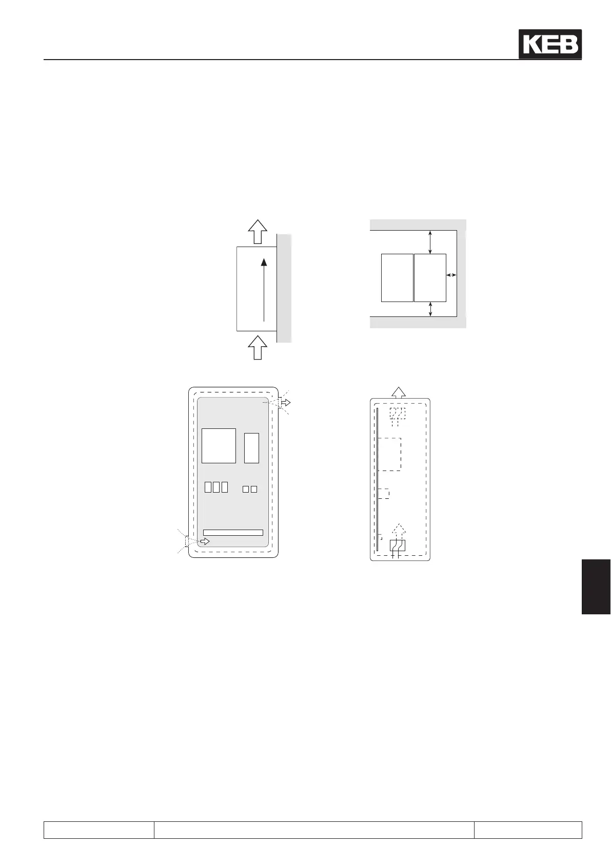
9.1.1 Control cabinet design calculation
Direction of
cooling ns
F5
F5
Minimum distances
KEB
COMBIVERT
Warm air
outlet
Cool air inlet
Control cabinet surface
Calculation of control cabinet surface: Air ow rate with fan cooling:
P
V
————
∆T • K
3.1 • P
V
————
∆T
A = [m
2
] V = [m
3
/h]
A = Control cabinet surface [m
2
]
∆T = temperature differential
(standard value = 20K)
[K]
K = coefcient of heat transmission
(default value = 5)
P
V
power loss (see technical data)
V = air ow rate of fan
For more details please refer to the catalogs of the control cabinet manufacturers.
 Loading...


