Page 7.13 - 20 COMBIVERT F5-A, -E, -H © KEB, 2012-10
Protective functions
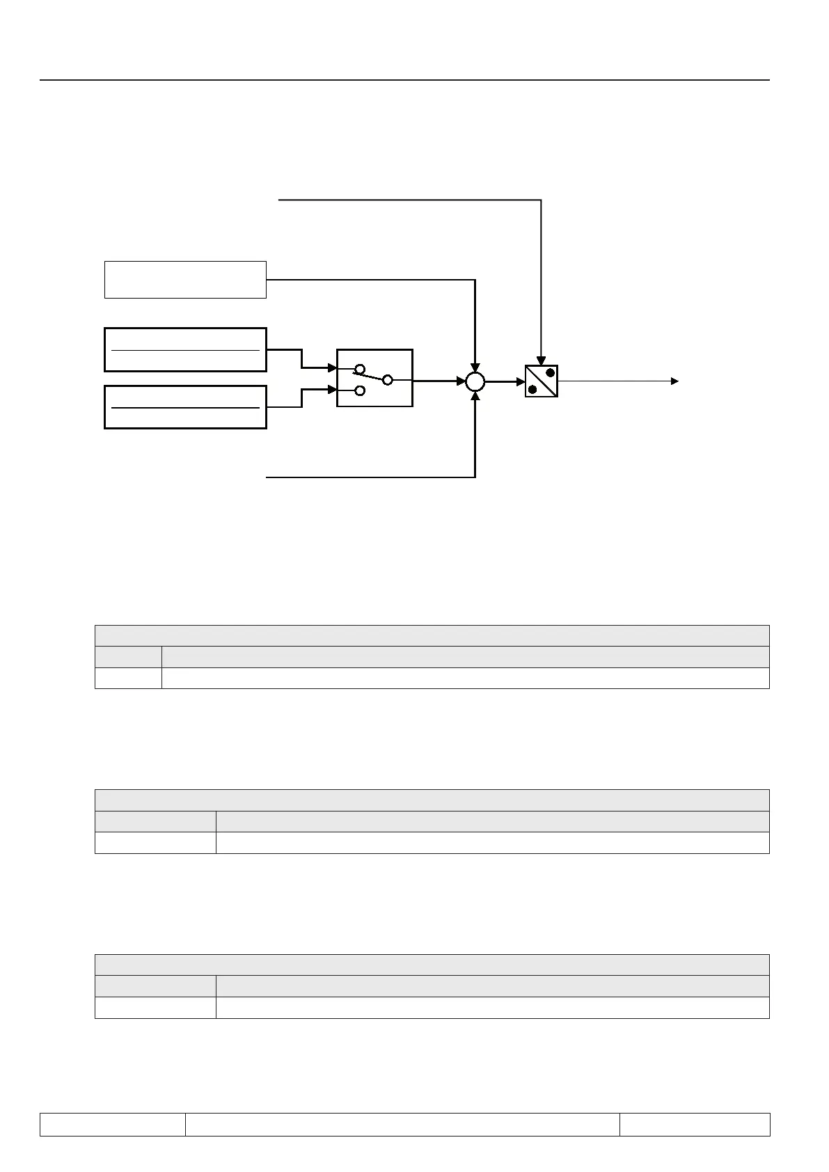
Block diagram of the differential control:
-
1
0
1
+
+
Actual ramp time
Quick stop dec time (Pn.60)
Quick stop level (Pn.59)
Quick stop mode (Pn.58)
Bit 0
Apparent current (ru.15)
Rated inverter current (In.01)
Active current (ru.17)
Rated inverter current (In.01)
7.13.5.2 Quick stop at closed-loop systems
For abnormal stopping with closed-loop systems, the drive is decelerated with the adjusted ramp time, and at
the torque limit, respectively.
Pn.60: Quick stop deceleration time
Value Explanation
0...300 s Deceleration ramp for abnormal stopping-function
For the abnormal stopping, the "normal" torque limitations of the application often do not apply since the auto-
matic shutdown is always a malfunction response. To permit a quicker deceleration with a greater torque here,
there is a unique torque limit for abnormal stopping.
Pn.61: Quick stop torque limit
Value Explanation
0...32000.00Nm Quick stop torque limit
The torque limitation superimposed by the limiting characteristic and the available current remain in effect.
For asynchronous motors, the maximum cutoff torque for abnormal stopping can also be increased to make
more torque available for braking, even in the eld weakening range.
Pn.67: Quick stop maximum torque corner speed
Value Explanation
0...32000.00Nm the limiting characteristic for abnormal stopping is dened by dr.16 instead of Pn.67
 Loading...


