Page 7.3 - 32 COMBIVERT F5-A, -E, -H © KEB, 2012-10
Digital in- and outputs
Description
For the switching of the digital outputs one can choose up to 8 conditions from the 91 different conditions.
These are entered in do.00...do.07. Switching condition 0 and 1 can be ltered by do.43 and do.44. Parameter
ru.23 displays, if one or several of these conditions are met . For each ag it can now be selected which of the 8
conditions shall apply to it (do.16...do.23). Each condition can still be inverted before selection (do.08...do.15).
As a standard all conditions (if several are selected) are OR operated. With do.24 this can be changed to AND-
operation . i.e. all conditions selected for this ag must be fullled before it is set. Parameter ru.24 displays the
ags which are set in this stage. do.33...40 form a second logic step where a selection of the ags from logic
step 1 can be made. Each individual ag can be inverted with do.25...32. do.41 adjusts the type of the linkage
(AND/OR). Parameter do.42 is used for inverting one or several outputs. With do.51 the output signals are
assigned to the terminals. ru.80 serves for the display of the digital output state, thereafter ru.25. The internal
outputs OA...OD are directly connected with the internal inputs IA...ID.
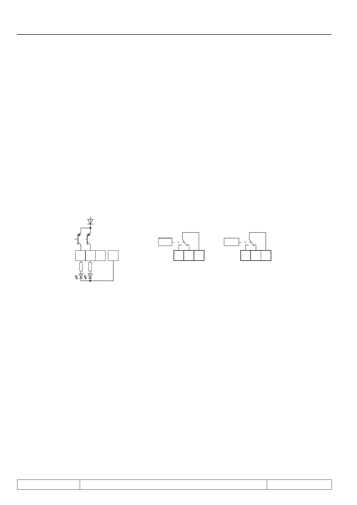
7.3.15 Output signals / hardware
Fig. 7.3.13a Transistor outputs Fig. 7.3.13b Relay outputs
The total current of X2A.18,19 is limited to 50mA. In case of inductive load at the relay outputs or at the transi-
stor output a protective wiring is to be provided (free-wheeling diode)!
7.3.16Outputlter(do.43, do.44)
A lter can be set for switching condition 0 with do.43. For switching condition 1 with do.44. The change of a
switching condition must be applied for the lter time, then it becomes active at the output of the lter. If the
change of a switching condition is cancelled during the lter time, the lter time is reset and restarted with the
next change. The lter time can be adjusted in a range of 0 (off)...1000 ms.
 Loading...


