Page 3.1-4 COMBIVERT F5-A, -E, -H © KEB, 2012-10
Control Units
24
25
26
27
28
29
Relay 1 / NO contact
Relay 1 / NC contact
Relay 1 / switching
contact
Relay 2 / NO contact
Relay 2 / NC contact
Relay 2 / switching
contact
RLA
RLB
RLC
FLA
FLB
FLC
Programmable relay output 1 (Terminal X2A.24...26);
Programmable relay output 2 (Terminal X2A.27...29)
Specications, control and programming of the relay outputs
see chapter 7.3.12...7.3.22
max. 30 V DC, 0,01...1 A
3.1.2 Connection of the control
In order to prevent a malfunction caused by interference voltage supply on the control inputs, the following
directions should be observed:
Use shielded/drilled cables,
lay shield on one side of the inverter onto earth potential,
lay control and power cable separately (about 10...20 cm apart);
lay crossings in a right angle
EMC
3.1.3 Digital inputs
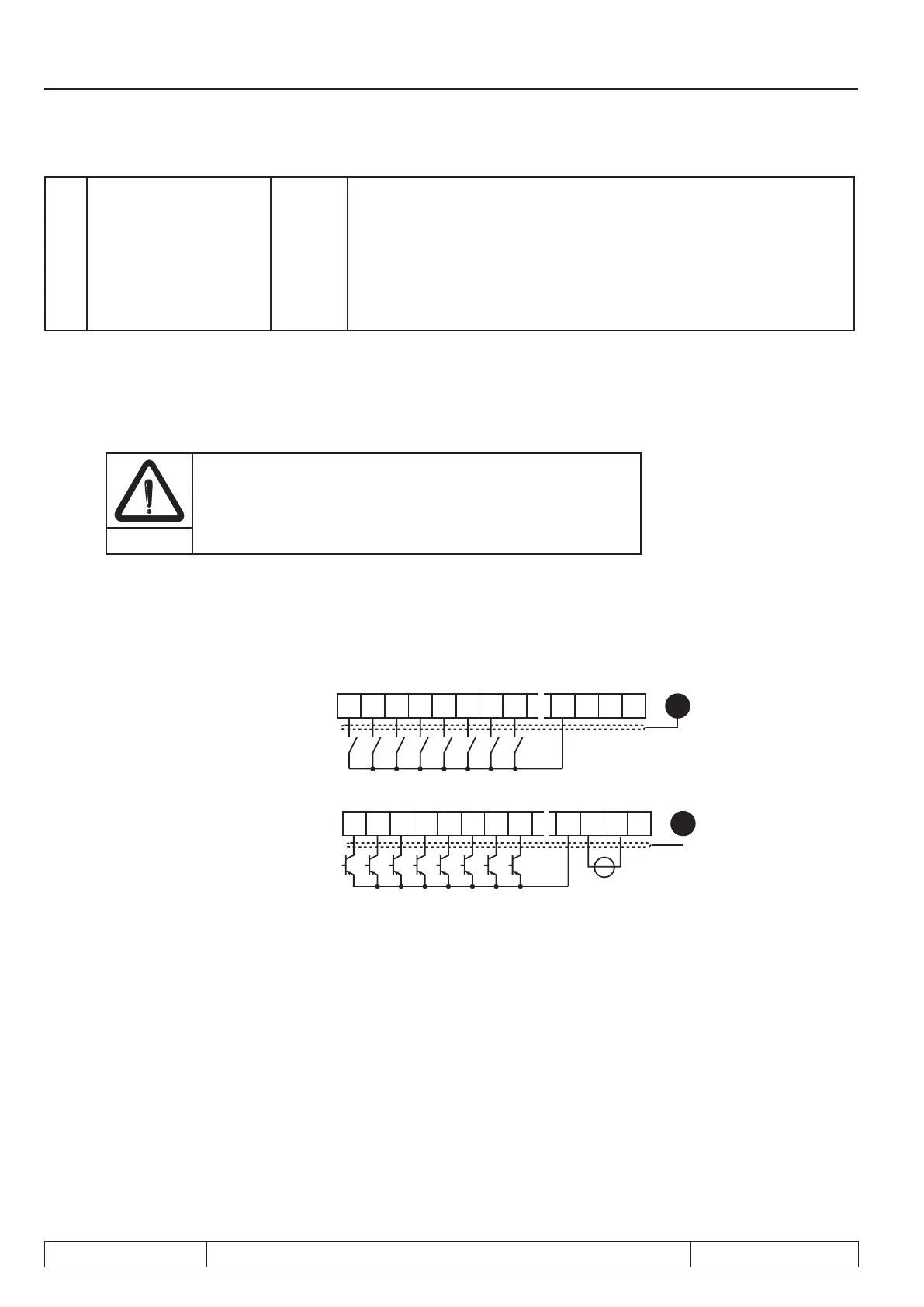
Picture 3.1.3.a Digital inputs with PNP control (di.00 = 0)
Internal supply
10 11 12 13 14 15 2016 17
I1 I2 I3 I4 FR GNDSTRST
PE
X2A
22 23
24V
out
21
24V
in
10 11 12 13 14 15 2016 17
I1 I2 I3 I4 FR GNDST
RST
PE
X2A
22 23
24V
out
21
24V
in
+
R
i
(digital inputs)= 2.1
kΩ
External supply
Control voltage for digital inputs = 13...30V DC ±0% smoothed
 Loading...


