7.12.4.4.2 Positioning by the output
The position control is done directly on the value of the output encoder. I.e., the position values refer to
the position of the load.
Number of increments per load revolution = "encoder increments per revolution" (output encoder) x 2
"multiple
evaluation"
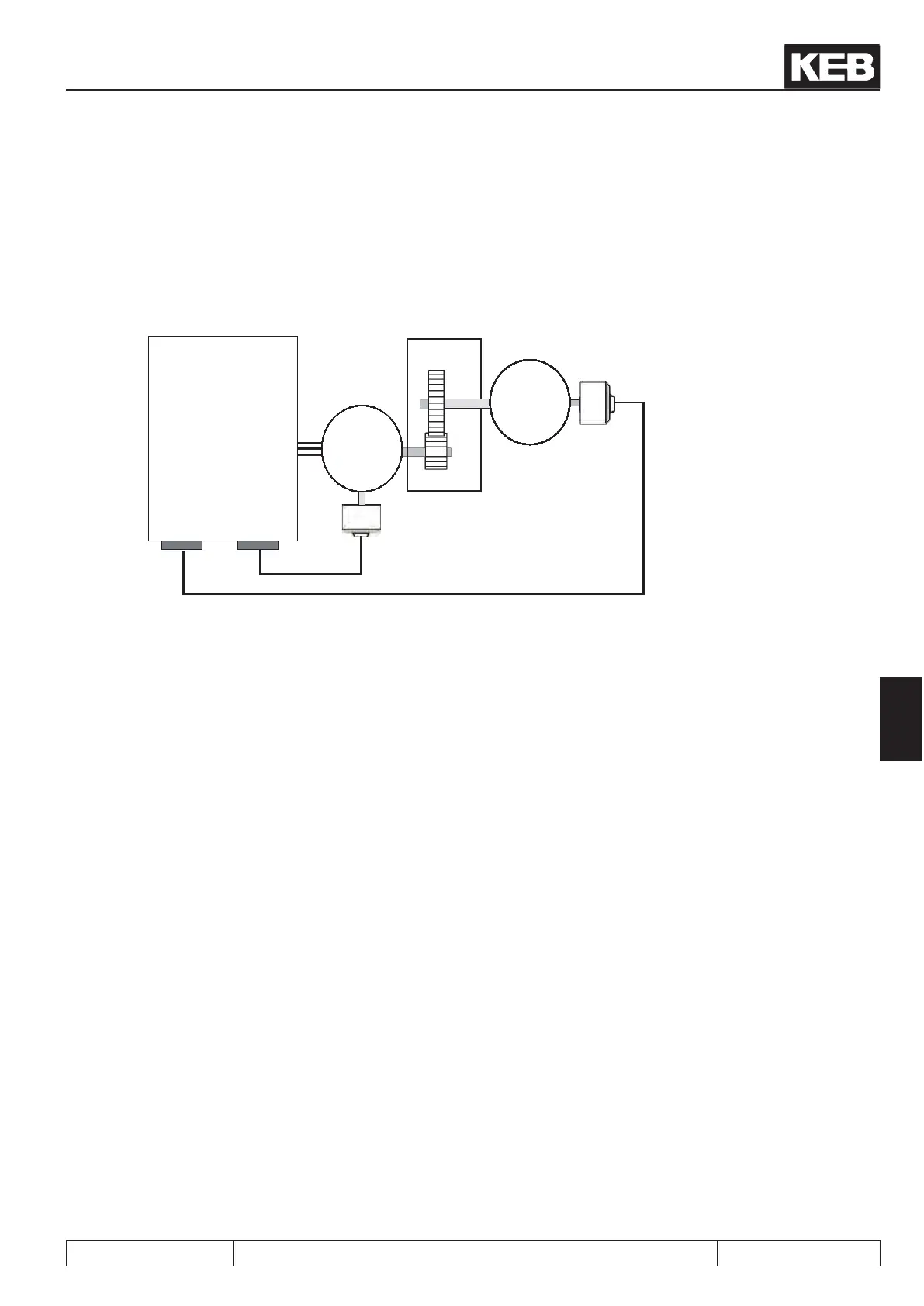
. Typically, the encoder interface 1 (X3A) is used for the motor position encoder and the encoder
interface 2 (X3B) for the output encoder.
KEB COMBIVERT
F5A-S
or
F5A-S
X3B
Encoder
channel 2
X3A
Encoder
channel 1
M
3~
Motor
encoder
Last
Output
encoder
Gear
1
3
To allow calculation of the speed precontrol prole for the speed control, the gear factor
between motor and load must be known, to convert the precontrol prole to the motor speed.
The speed limits and the values for maximum prole speed (PS.25) and maximum position control effect
(PS.09) refer to the motor speed.
Example:
Encoder channel 1: Incremental encoder with 2500 increments per revolution
Encoder channel 2: SSI encoder multiturn with 12bit resolution per revolution and 12bit multiturn
Gear ratio: 3 motor revolutions cause 1 load revolution
cS.01: actual source = 0 Channel 1
Ec.01: encoder 1 (inc/r) = 2500 Line number
Ec.07: Enc. 1 trigger = 2 4-fold evaluation
PS.01: Actual position source = 1 Channel 2
Ec.11: Encoder 2 (inc/r) = 1024 12 bit resolution per revolution
Ec.17: Enc. 2 trigger = 2
Ec.21: SSI Multiturn-resolution = 12 12 bit Multiturn-resolution
Ec.14: Gear 2 numerator = 3000 Gear factor =3
Ec.15: Gear 2 denominator = 1000
The load shall travel 5.5 revolutions: 1024 x 2
2
x 5.5 = 22,528 increments
Posi- and synchronous operating
© KEB, 2012-10 COMBIVERT F5-A, -E, -H Page 7.12 - 31
7
 Loading...


