Analog in- and outputs
© KEB, 2012-10 COMBIVERT F5-A, -E, -H Page 7.2 - 15
7
7.2.13Amplieroftheoutputcharacteristic(An.33...35/An.38...40/An.43...45/An.49...51)
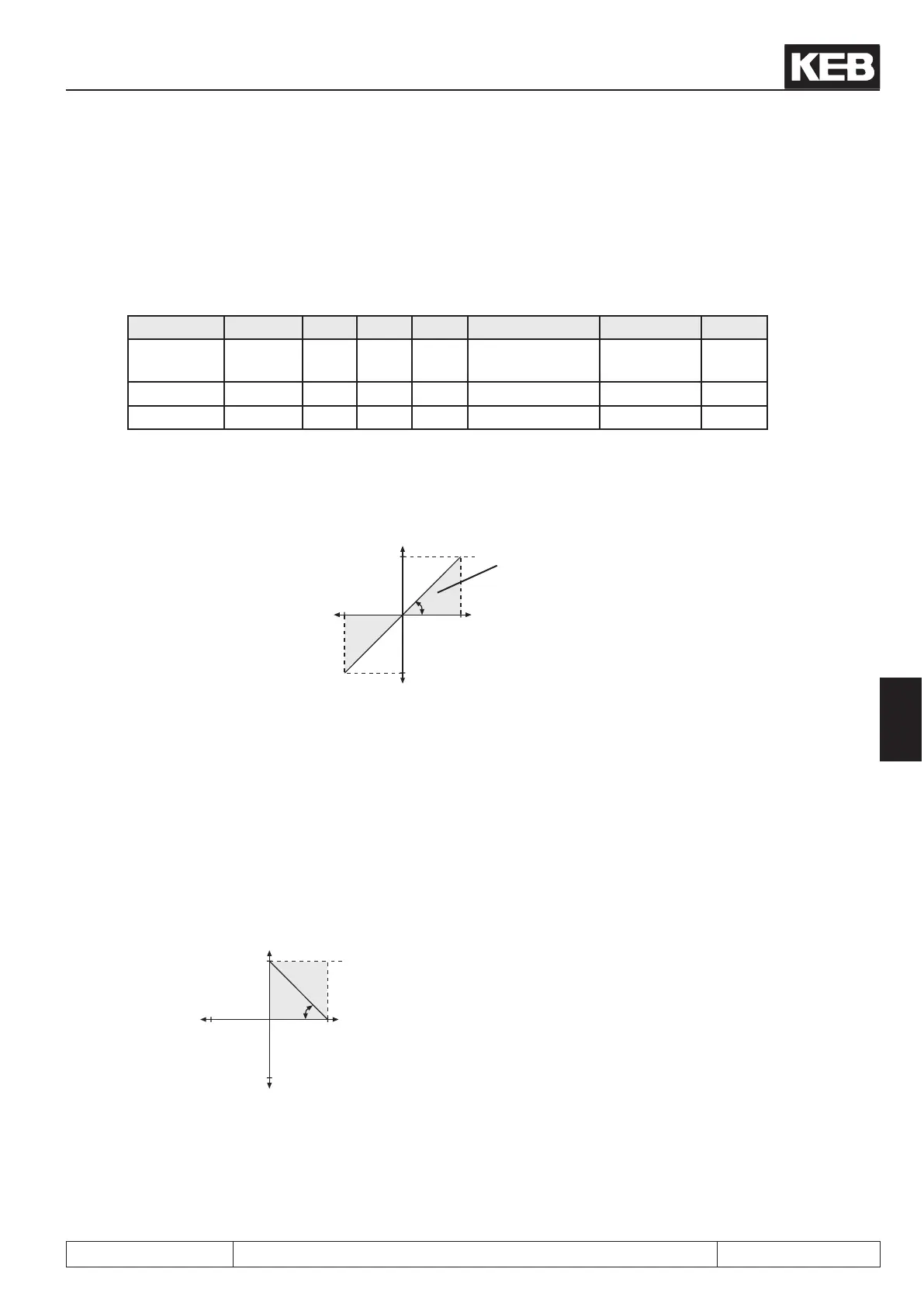
The characteristic amplier are following after selecting the signal to be given out (see Fig. 7.2.9). With these
parameters the input signals can be adapted in X and Y direction as well as in the rise to the requirements. No
zero offset is adjusted at factory setting, the gain is 1, i.e. 100% of the output variable correspond to 10V at the
analog output (see g. 7.2.14.a).
Function ANOUT1 -2 -3 -4 Value range Resolution Default
Amplifica-
tion
An.33 An.38 An.43 An.49 ±20,00 0,01 1,00
X-Offset An.34 An.39 An.44 An.50 ±100,0% 0,1% 0,0%
Y-Offset An.35 An.40 An.45 An.51 ±100,0% 0,1% 0,0%
Fig. 7.2.13.a Factory setting: no Offset, Gain 1
Output voltage
10V
100%
-100%
-100%
An.33
An.34
An.35
100%
displayable
range
variable to be indica-
ted
Inverting the analog output
An example for using the characteristic amplier is shown in Fig. 7.2.14.b:
1. adjustment of the X-Offset (An.34) to 100 (%)
2. adjustment of the amplication (An.33) to -1.00
Picture 7.2.13.b Inverting the analog output
10V
100%-100%
-100%
An.34
An.35
100%
An.33
These settings result in an inverting of the analog signal.
0% corresponds to 10V at the output
100% corresponds to 0 V at the output
 Loading...


