4-3
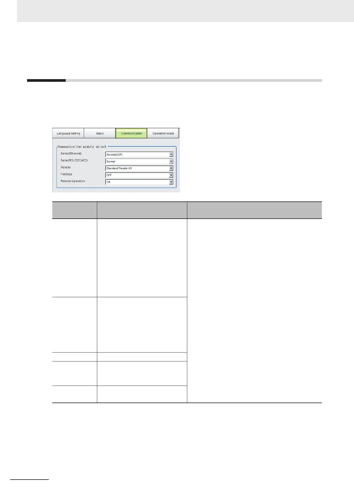
Setting Communication [Startup Set-
tings]
Select the type of Communications Module to determine the communications method to use for com-
munications between the Sensor Controller and external device.
Refer to the Vision System FH/FHV Series User's Manual for Communications Settings (Cat. No.
Z342) for details on how to select the Communications Module.
Item
Set value
[Factory default]
Description
Serial (Ethernet)
• [Normal (UDP)]
• Normal (TCP)
• Normal (TCP Client)
• Normal (UDP) (Fxxx series
method)
• PLC Link (SYSMAC CS/CJ/CP/
One)
• PLC Link (MELSEC QnU/Q/
QnAS)
• PLC Link (JEPMC MP)
Specify the Communications Module.
• Serial/Ethernet
Normal/Normal(Fxxx series method): Communica-
tions are performed with external devices through
non-procedure communications. For differences be-
tween Normal and Normal(Fxxx series method), re-
fer to the following note.
PLC Link: Communications are performed through
link areas with the PLC.
Touch Panel Monitor (FH-MT12): Communicate with
Touch Panel Monitor (FH-MT12). FH-MT12 is sup-
ported only by the FH series Sensor Controller.
• Parallel
Standard Parallel I/O: Communications are per-
formed with a standard parallel interface.
Fieldbus: Communications are performed through
EtherCAT communications and the EtherNet/IP in-
terface.
Remote operation: The Controller is operated from
an external device.
Serial
(RS-232C/
RS-422)
• [Normal]
• Normal (Fxxx series method)
• PLC Link (SYSMAC CS/CJ/CP/
One)
• PLC Link (MELSEC QnU/Q/
QnAS)
• Touch Panel Monitor (FHMT12)
Parallel [Standard Parallel I/O]
Fieldbus
• [OFF]
• EtherCAT
• EtherNet/IP
Remote Opera-
tion
• [ON]
• OFF
4 Setting the Controller
4 - 6
FH/FHV Series Vision System User’s Manual (Z365-E1)

 Loading...


